Week 9 | Input Sensor


NOTES

make -f hello.button.44.make
sudo make -f hello.button.44.make program-usbtiny-fuses
sudo make -f hello.button.44.make program-usbtiny
get pip
sudo easy_install pyserial
sudo python output.44.py /dev/tty.usbserial-AFV7I77P
Helpful Websites:
Input Devices
clocks (10% RC, 1% RC calibrated, .5% resonator, 50 ppm crystal)
- different way to tell time.
light sensor
- sensitivity determined by a pull up resistor
- bigger resistance is sensitive to small changes in current, l
temperature sensor
- best if use a bridge to find see changes at a smaller range
step response sensor
- can figure out if things at the electrode is a series or parallel
resister/capacitor via step response
- humans are series our body is the resistance and capacitance between
us/feet to ground)
synchronous under sampling
- can step high then step low and see the noise level
- charge up and measure then discharge and measure
- difference between them is due to noise
(adding first order cancels them)
- this removes background noise
sound sensor
- problem is noise and measuring a very low voltage
- need a clean v_ref done by voltage regular
sonar
- acoustic proximity sensor
- time in return gives you distance. Need two to ring off each other
Filters
Passive Filters
Active Filters
Digital Filters
Why filters at all?
- When making measurement there is usually stuff you don't want.
- High frequency noise (filter helps separate that noise)
- Or improve resolution (want more digits of accuracy)
- At low frequencies there are varying baselines
- Advanced filter is getting 1 signal from many
Once your signal is strong enough than you can do everything in the digital world for filtering
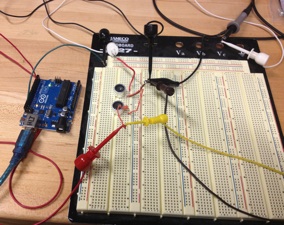
Phase 1: Getting to know my sonar sensor

Setup:
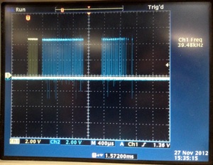
-Using Arduino to send 40kHz pulse trains. (10 pulses every 10 milliseconds)
-Reading analog out of the receiving sonar via Oscilloscope
Learned:
-Correct delays to achieve 40kHz
-Made sure that transmitted signal is able to be picked up by the receiving sonar
Phase 2: Digitally reading sonar receive signal

Setup:
-Using Arduino to send 40kHz pulse trains. (10 pulses every 10 milliseconds)
-Reading digital out of the receiving sonar via Oscilloscope
-20x gain of differential input of the sonar with v_ref of 1.1v
(gain necessary for signal amplification
v_ref necessary to have a better window of resolution)
-Output a high signal whenever input differential signal is above
empirically determined threshold
Learned:
-Played with the pre-scaler of the ADC to see how fast you can sample the
output signal. Data sheet said: "It is not recommended to use a higher
input clock frequency than 1 MHz.” But got away with 20Mhz/8 or 2.5MHz
-Figured out a threshold (where you know you are getting the signal
response of the sonar transmitter and not noise)

Future Work/Wishes
ToDo:
-
1) Have ATtiny44 produce the pulse train for transmitting sensor (DONE)
-
2) Figure out time difference from input signal to output signal (DONE)
-
3) Print PCB board (DONE)
-
4) 9V power supply + mosfet for higher sonar signal out
-
5) Lower v_ref (more sensitivity, voltage divider)
-
6) Map timing to distance and calibrate
Files

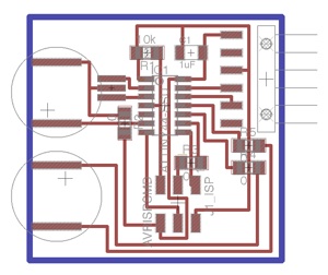
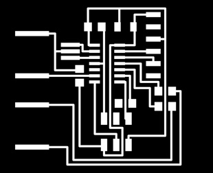
Phase 3: PCB layout

Phase 4: sonar.44.c

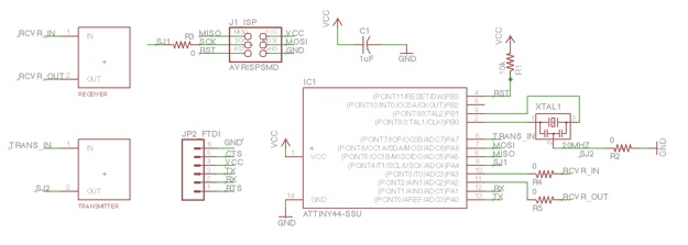
Learned the following:
-
1)Sending out 40hz pulse train using 12.5us sleep delays
-
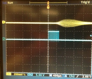
2)Figured out how much delay is necessary to pass the first wave of noise resonance (see figure above, yellow is pulse train, first blue chunk is the noise)
-
3)Found appropriate sampling window
-
4)Determined how much time from transmission to first read-back
-
5)Figured out how much delay is necessary to move past the first ringing to send the next