Week 5 | Electronics Design


NOTES

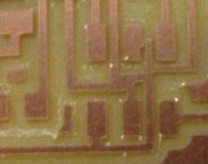
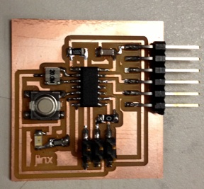
Final Results - Version 1 - FAIL

Helpful Sites
Electronic Software
Cad/Syn/mentor expensive
Spice for simulation (if you are really honing down for noise or power)
Verliog VHDL for programming IC
Electronic Components
Capacitor
V_dot * C = I (derivate of Q) ie current driven by change in voltage
act as a filter
stores energy and charge instantly (battery)
Inductor
Opposite of capacitor
V = L * I_dot (derivate of I) ie voltage driven by change in current
Choke high frequency data
Diodes
anode to cathode
Schottky
Zener - used to clip a voltage (which voltage it turns on)
LED - a diode that glows
all just have different V/I curves
Mosfets
look like variable resistors (transistor that variables resistance)
Regulators
like zener but better at voltage control
Opamps
difference between voltage
negative feedback turns into integrator or differentiators
can also be used for gaining
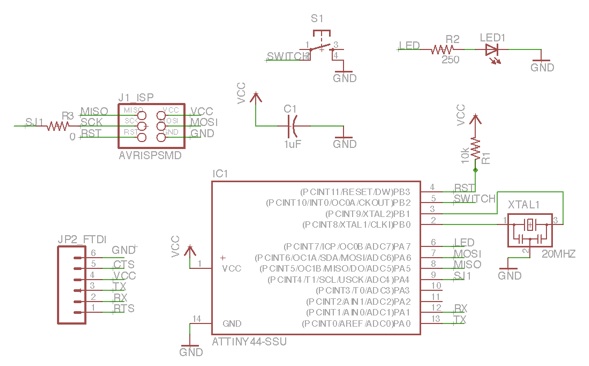
Eagle
Open both schematic and board layout at the same time.
Grid Size: .025 in Pitch 2x
Track Width = 0.016 in
Show only Top layer for circuit
Show only Dimension layer for cutout
File -> Export -> Image
Select monochrome
Set to 1500 dpi
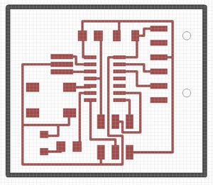
Board Design - Version 1 - FAIL

Problem
Solution
- Resized Grid to .025 and Pitch 2x
- Also added a zero ohm resistor to do a trace jump


Board Design - Version 2 - SUCCESS

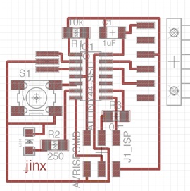
Final Results - Version 2 - SUCCESS

Problem
-Bad solder connection on the button leads
Solution
-
-Removing solder with wick
-
-Smoothing over connections till nicely shiny
Future Work/Wishes

-
1)Gain better circuit design intuitions and solving circuits
-
2)For halloween making sequence of blinking colored LEDS