
Week Eleven: Output Devices
dance dance re-revolutionizing
Task
Add an output device to a microcontroller board and program it to do something.
Result
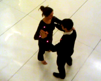
This week I continued to build on my ballroom dance partner peace mediating system from week 9. When dancing, you need to know what foot your weight is on and disagreements on this often cause arguments between partners. My shoe pressure sensors determine how each dancer is standing. I created a board that can attach to a few different output devices to display that information, including LEDs, Piezo buzzers, and RGB LED.
I created two copies of the system in order to display the real life application. Here it is in action:
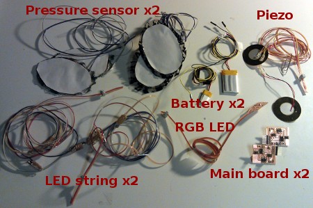
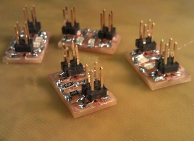
Here are all the parts of the system:
Files
Here are the board and code files for the various sensors:
Approach
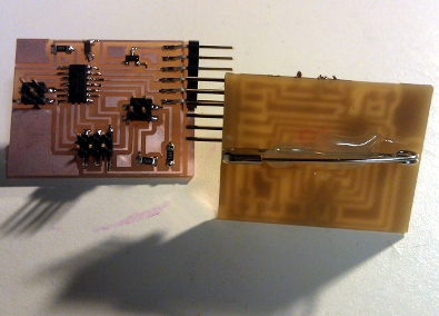
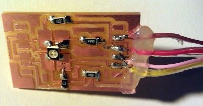
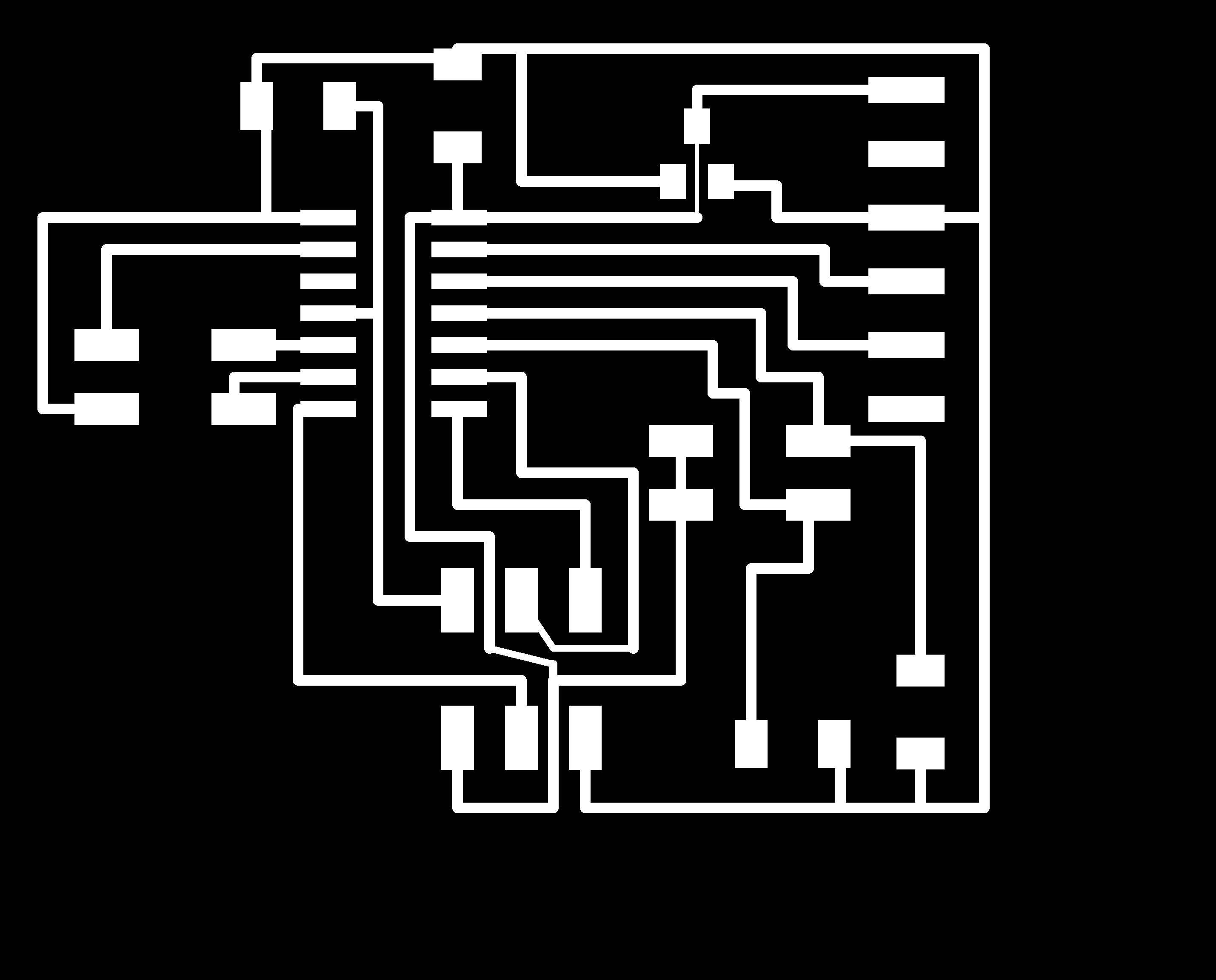
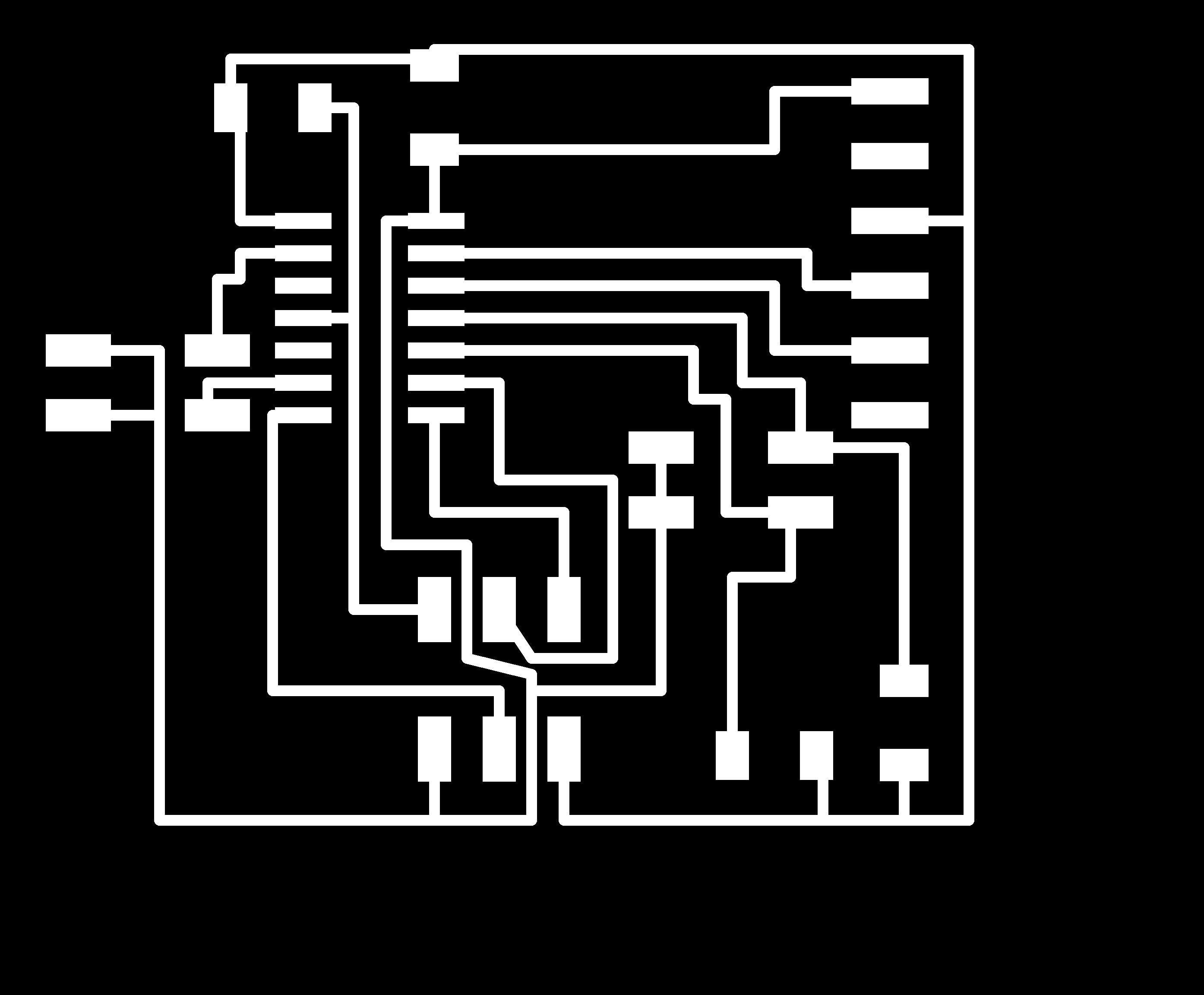
I created my board using Eagle and building from my week 9 board. I added a 5V regulator and reorganized the output pins to allow for the RGB LED attachment. I milled and stuffed the board with the Roland Modela as usual.
I made some modifications to the form of my input and output devices based on previously encountered usability issues. I used PCB boards instead of vinyl cut circuits and added headers so the attachments could be easily removed from and added to the main board. I hot glued safety pins to the back of the boards to increase the ease of use. I also made my pressure sensors as shoe inserts instead of trying to permanently attached them to the shoes and socks of the user.
I adjusted my code from past weeks to the new pin configuration and combined it with the RGB LED code to created a program for each output device paired with the pressure sensors. I followed the usual procedure to upload my code.
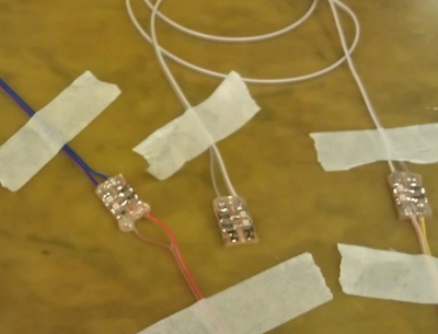
With everything working smoothly on the tabletop, I again tried to implement it in my real world ballroom dance application with two users. Though I hot glued safety pins to the back of the boards, elastic or snap bands might be a better way to connect the boards to the users. The pressure sensors insert into shoes and the wires are pinned down occasionally, though eventually they could be worn inside the clothing, integrated into the clothing, or switched to a wireless system. It worked pretty well this time around!
Thanks to Sam for videoing and Jorge for dancing.
Trials and Tribulations
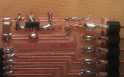
I tried running my voltage-regulator-free board off a lithium battery in week 9 without any trouble, but decided this was probably just good luck and I should do surgery to add to part to my old board. I used the copper braid to run a "trace" under the voltage regulator and employed all my fine motor skills to get it to work. It was also tough to run the traces on my new board under the 5V regulator from the footprint in the Fab library. After some trial and error it ended up working at 0.009 width in Eagle.
Later in my process, I realized the reason my original board worked off a battery without a voltage regulator was that my battery wasn't 9V as I thought, but 3.7V. I thought these were meant to run off 5V, but the 3.7V batteries seem to work, so I guess this is sufficient for my board (or just dumb luck?).
My pressure sensor is not completely reliable as the fabric isn't entirely uniform. This doesn't make a huge difference if reasonably even and strong pressure is being applied across it (stepping), but occasionally funny things happen when I pressed on it with my hand. The green lace fabric worked better than the black lace, as is evident in the video (Laura->green; Jorge->black). This was consistent with my week 9 testing results.
I had a bad experience ripping off traces from forces on attached wires in past weeks, so initially I switched to a header-centric design for this week. I like the flexibility in attachments this offered, but found the trade-off was remembering how everything was supposed to connect. The headers also ruined the profile of the LED boards, so I decided to take them off and give soldering and hot gluing another try. The process worked better the second time around for a few reasons: (1) the ribbon cable was more flexible than the wire I used last week (2) I brought the hot glue gun to the soldering station so I could hot glue immediately after soldering (3) my connections were better thanks to my tape-the-wires-to-the-table approach while soldering (4) I kept the headers to attachment the input/output devices to the main board--this made the system much easier to transport without parts getting caught or twisted up funny. I still ended up with one LED string that was slightly finicky, and unfortunately it was difficult to re-solder post-hot gluing. But overall this hybrid approach worked well.
It'll be great to go wireless in future weeks! There were some issues with cables getting stepped on.
The Fab library RGB LED has a footprint much larger than necessary for the part. I didn't notice this until after creating my board though.
There are still some coding things from week 9 I'd like to figure out--particularly pulling the difference between the two pressure sensor readings in the ADC process and getting the variable types correct so math in C works as expected.
Kdenlive refused to render my edited video if it included a title slide. I haven't had time to explore the broader issue behind this--and only managed to figure out the temporary fix to the problem through trial and error!