
Week Three: Electronics Production
burn baby burn...
Task
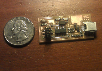
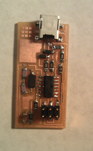
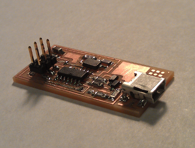
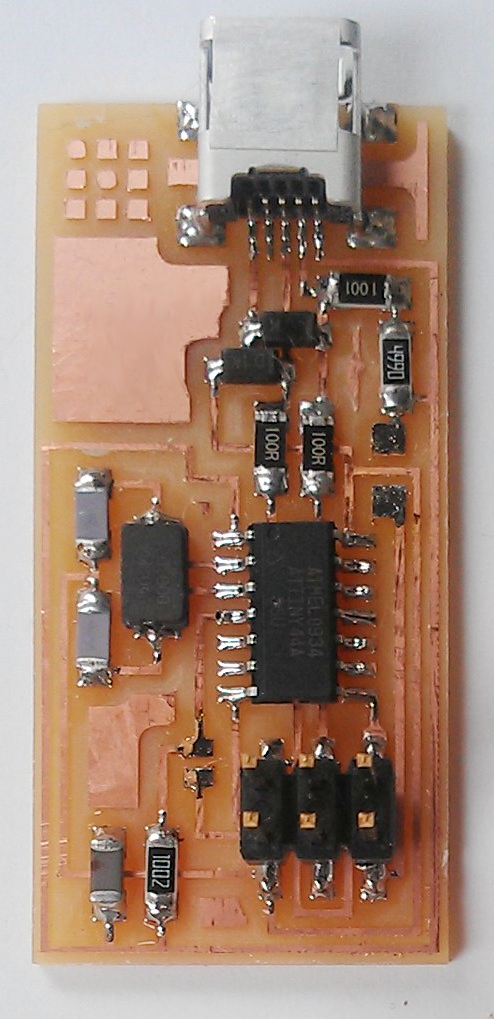
Make the FabISP in-circuit programmer.
Approach
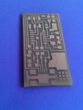
Milling the board
We used the Roland Modela milling machine with a 1/64th and 1/32 endmills to create the board from FR1 paper based copper plates from the trace and interior files provided. The steps in this process were:
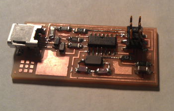
Stuffing the board
Trials and Tribulations
I started with a newer endmill and the cut turned out a bit jagged even thought I reduced the speed to 3.5. Gently sanding it down smoothed it out quite a bit. If it seems like the Modela isn't responding, make sure you're not in View mode.
Soldering these small components took some patience. A magnifying glass helped me to identify bridges and other issues. I also burned myself frequently--especially when removing solder--though I think my heat tolerance increased in the process. It was a bit difficult to juggle all the various tools while soldering though I think more practice will increase my ambidexterity and make life easier.