
Week Eight: Computer Controlled Machining
neither rain nor snow...
Task
Make something big.
Result
This week I wanted to make a mathematical table. The bottom surface would be an interesting function and the top surface would be the contour plot for that function. This would look particularly nice in glass. The legs of the table extend from the local maxima of the function.
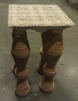
Hurricane Sandy derailed my plans a bit, but a few weeks later I finished up my table!
Files
Here's the code to create the stl files and bitmaps for the two-part mold, contours, and table legs:
Approach
Design
Because the wood was too thin for a 3D shape I decide to use the foam to create a mold for the table's surface. Gluing two pieces of foam together would get me about 4" of height to cast in Hydrostone.
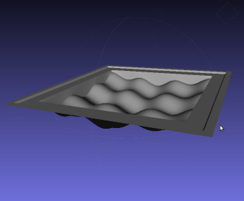
I designed the parts of the table in R in four steps. First I created the top and bottom of the mold. The bottom of the two-part mold was the 3D function. I tried out a number of surfaces, and both curved and square table shapes before deciding on -(cos(y)*cos(2y)+cos(x)*cos(2x)) from -pi to pi with a square outline. This gave me a nicely symmetric surface with a reasonable number of cycles, room for legs, and varying function heights. I then added two levels of square edges outside the function, for fitting the two parts of the mold and to provide the overall depth. I created the stl files using R functions I developed in past weeks.
Next I created a simple top to the two-part mold. This piece fits within the square edges of the bottom part of the mold. The interior surface is flat--after some thought it seemed easier to add the contours as a separate step instead of trying to include them in the stl file.
I didn't include holes for pouring, air release, or table legs in the stl files. It made more sense to do this by hand.
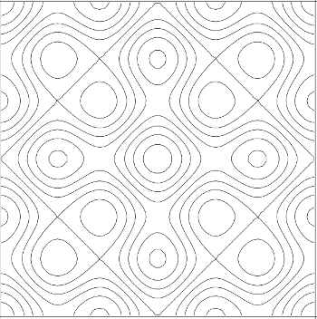
Then I created a bitmap of the contour plot for my function. I'll center this file at the inside edge of the top of my mold and limit the cut depth to add light contours on the top surface of the table. I also made a bitmap square to use an a cut path to remove the foam pieces so I can use them as molds.
Next I made a bitmap of the contour plot for my function. I'll center this file at the inside edge of the top of my mold and limit the cut depth to add light contours on the top surface of the table. I also made a bitmap square to use an a cut path to remove the foam pieces so I can use them as molds.
Finally I created disks of various widths to stack on dowels to create the legs of the table. Turns out I needed a lot of them (180!) to get the height I wanted off all four legs.
ShopBot
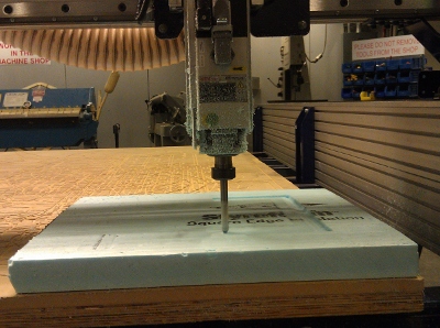
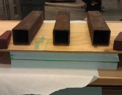
Foam was the best material for creating my molds, especially since I could glue two pieces together to get additional depth. I started by cutting the foam into three 2' square chunks. Tom helped me glue two together--use a roller to evenly coat both surfaces, let them sit open face for half an hour, stick the pieces together under weights for about an hour (or more).
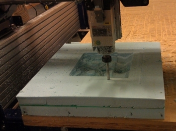
With the help of Tom, I used PartWorks 3D to turn my files into cut paths and the ShopBot console to cut. I also had to do a bit of resizing here. We used a 1/2" bit and selected a high step-over (12%) on the finish cut to save time, since time was short. The surface still turned out reasonably well though.
Prashant's page goes through many of the ShopBot details. I had just enough time to cut the top and bottom of the two-part mold, though I'll have to save the contour etching for another week. I didn't trim off the outside foam edges so I'll be able to re-attach the foam to the bed another time without adding interior holes.
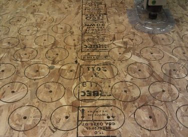
A few weeks later, I used the ShopBot again to cut the circles for the legs. Tom advised me to redo the file using Rhino to get nicer shapes than the bitmap would provide. He also helped me auto rearrange the circles in PartsWorks and add tabs to keep the circles in place throughout the cut.
The tabs worked out really nicely! I used the belt sander the clean up the edges of the cut circles. This was somewhat time consuming but satisfying.
Casting
After seeing Carlos' experience picking out foam from his cast, I was eager to seal my mold as well as possible. I heat gunned the whole thing (partially in the fume hood--these fumes cannot be remotely good for you) and then coated it liberally in Vaseline (a lot!).
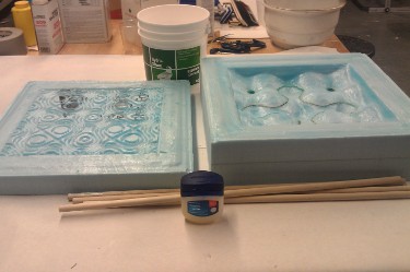
I lightly taped over the holes for the dowels and poured the hydrostone in the bottom and top of the mold. I did the hydrostone in three mixes, but tried to minimize the time between each layer. Sam helped me flip the two pieces of the mold together, then turn the whole thing over and insert the dowels. Kind of a mess, but in the end the leakage was minor. It helped that the hydrostone had just started to dry so small cracks sealed themselves within a few minutes.
I opened the top of the mold after 24 hours--while it was dry enough to easily keep its form, it was still quite warm and a darker grey, so I decided to leave the bottom for a bit longer. After another 48 hours I took off the bottom piece. Overall this process went quite well. The molds were only slightly banged up in the removal process. The Vaseline did make the surface a bit irregular. Next time I'll try brushing it on so there won't be chunky parts.
I did another mini-round of hydrostone to fill in some bumpy parts of the cast--especially where the foam had been glued together and the dowels inserted into the hydrostone. It was helpful to let the hydrostone solidify just a bit before applying it.
I stacked the circles on the dowels. The fit was nice, so I only wood glued the bottom few to hold everything in place.
Trials and Tribulations

Hurricane Sandy closed MIT and the shop on Monday when I was scheduled to use the ShopBot, so I only made to two-part contour-free mold. Thanks to Tom and John for helping fit us all in on Tuesday! I finished up the contours, legs, and casting later in the semester.
Using R to model this object took a lot of planning, but I still prefer it to the CAD programs I've met so far.
But...PartWorks 3D wouldn't take my stl file because it was a surface not a solid. This is frustrating--I need to figure out a R-based solution for this. I used my work-around from week 4 as a quick fix: import to MeshLab, Filter->Remeshing->Uniform Mesh Resampling with settings precision at 1.0%, offset at 53.0%, and absolute distance selected. This gave me a solid, but unfortunately also threw off my dimensions--in particular, my z-dimension increased past the thickness of my foam. I suspect reducing the offset would have decreased the change in dimension, but my two hours was ticking away so I didn't have time to mess with it. Instead, I reduced the dimensions in PartWorks to a 16"x16" square with 3.44" depth (original wanted a 22" by 22" square). Rescaling the intended dimensions of my other pieces (except the legs) by 16/22 should keep things on track.
The table is certainly not a vision of structural integrity. Maybe a different approach for attaching the legs next time.