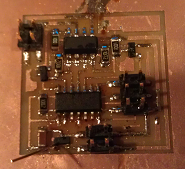
I decided to create a DC motor controller board using a H-bridge chip
After
milling and populating the board, I noticed that when I supplied 12V
power to the board, I was measuring only 0V at the connector. For
some reason, the board was drawing the 12V to 0. I learned that
this was due to my use of a MOSFET instead of a 5V regulator chip.
After replacing that, I was able to see the appropriate voltages
at the Vcc points of the board. After that I was able to use
Avrdude to program the fuses, but when I programmed the motor control
code, I got an RC-1 error. I was not able to find any shorts in
the board. I tried replacing the microcontroller but that didn't
help either. At one point, I accidentally plugged the power into
the motor connector and it cause the board to draw the power supply
connected to it to 0V again.
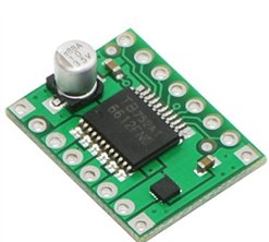
At this point, I decided to use an off-the-shelf motor driver instead.
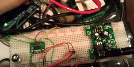
After making all the connections as specified, I was able to write a simple PWM sketch on Arduino to contorl the motor: