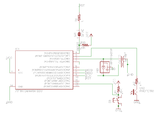
My project is to intergrate a tactile button and LED with the ATTINY microprocessor. After laying out this main board, I had wanted to add a microphone so that I can create a pitch or sound meter. Then I realized that the buffer circuit required would have required a complete reroute of the board, so I left it out for now. Lesson for the future is that adding components to a single layer board is not trivial.
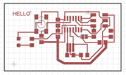
I had used a software called Multisim for schematic capture before, and found that to be much more intuitive than the Eagle software. Regardless, after getting used to the quirks of the new software, I learned a lot about laying out a board and how to leverage tools such as Ratsnest and why "rip up" is needed to get rid of routes (keeps the backward notation with the schematic).
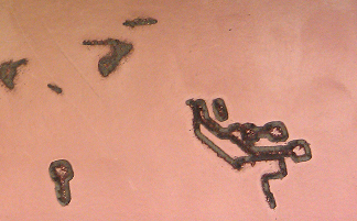
I spent a lot of time milling the board. My repeated mistake is forgetting to set the mill to the 1/32 mill settings, hence the routes were going too deep regardless of the Z axis distance. Since the routes are relatively thin, the deep milling left mostly burrs instead of complete routes:
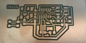
After realizing my mistake and becoming very good at cancelling jobs and positioing mill bits, I was satisfied to see my layout turned into reality:
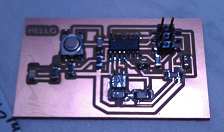
Unfortunately, during population of the board, I realized I had shorted power with ground at one point (after replacing a part last minute). I did some quick surgery to cut the routes and use solder to create some new connections. I like how the board resembles a small city:
Lessons that I learned from this:
i) Confirm schematic before layout. It is quite painful to reroute after you have optimized the board layout.
ii) Turning Ratsnest feature on will make layout much more pleasant
iii) Pressing Alt then routing will allow you to bypass snapping to the grid so youc can have more flexibility in routing