| Qty. | Description | Purpose |
| 1 | Pump | Circulate water to top resevoir |
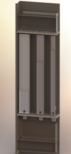
| 6 | DC Solenoid Valves | Control column water inflow and outflow |
| Tubes | Circulate water from botton to top resevoir | |
| 3 | Distributed Controller Boards (based on Neil's Step Response board) | Control water level of each column |
| 1 | Master Controller Board | Keep time and send command to column |
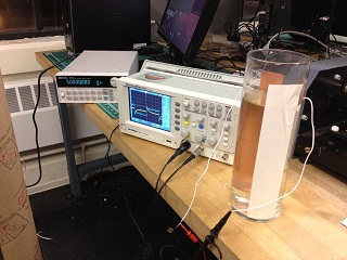
| 3 | Sensors | Feedback on water level |