This week, I'm making an interface where you can paste in python code to serve as the vehicle's 'brain'. The vehicle will send sensory inputs to the computer, and receive motor outputs in real time, based on the python code. I'm planning to use this programmable vehicle as my final project. It may be incorporated into a new undergrad neuroscience course
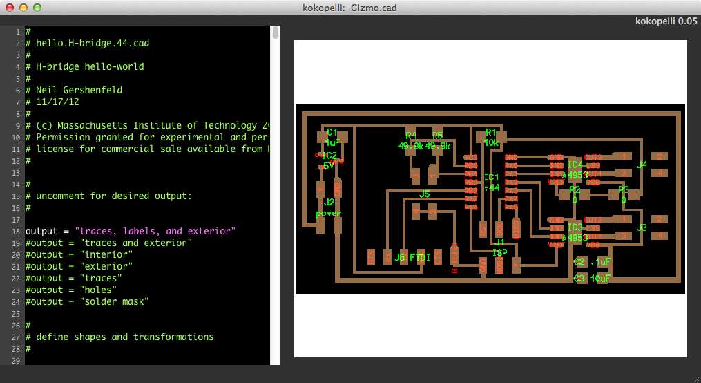
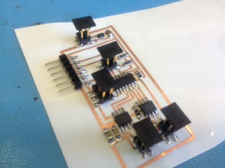
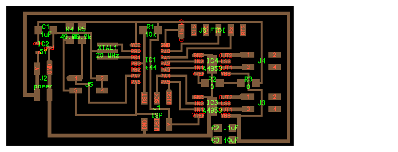
First things first, I wanted to improve on my vehicle from last time, which could only orient, not move forward. I made a .cad board with connections for two DC motors, power, sensors, the fabISP, and the FTDI cable to the computer:
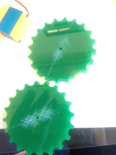
I scored the wheels, so the glue would stick better (it had fallen off once last time):
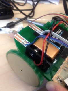
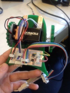
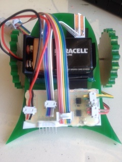
The DC motor works (see right wheel in the first picture below), but the motor is not strong enough to move the vehicle, because when you place the vehicle on a surface, its weight prevents the motor from moving (see second picture below).
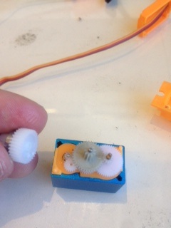
Therefore, I replaced the DC motor with the motified servo, which has gears to increase its torque (see last week's writeup). Following what Valentin showed me, I cut off the key on one of the gears, and bipassed the circuit to just connect the leads to DC motor.
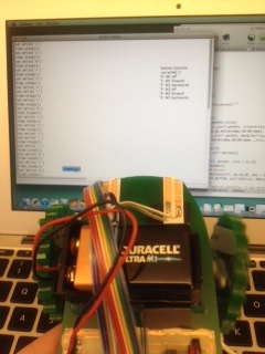
This helped, so now I moved on the programming it. I tried out Neil's TxRx board. Without the external clock, I got some gibberish at first, because the baud rate wasn't matched up right:
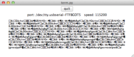
I changed the bit delay time in the .c file (because the chip clocks can be a bit inconsistent). This helped a bit, but there was still gibberish. This is what I got when I typed the alphabet:
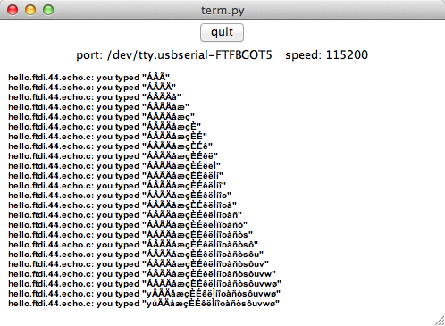
Then, I switched the baud rate to 9600 (I set the bit delay time to 100us), and it worked! Here's the command I ran to start Neil's term.py python program: python ../term.py /dev/tty.usbserial-FTFBGOT5 9600
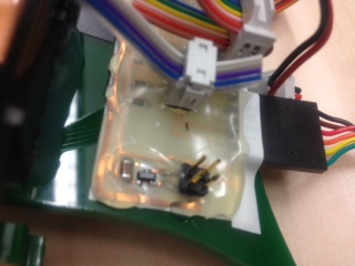
Side note: Don't plug in the FTDI cable when the battery is not plugged in. This will make the voltage regulator heat up, because it has 5V across it the wrong way (alternatively, I should have disconnected the 5V of the FTDI cable from anything, because it's not necessary, because it's not used to power the board). With only the FTDI cable and not the battery plugged in, the regulator heats up a lot, and melts the hotglue:
Another note: Don't use the PB pins on the attiny for things you need an ADC for. I thought it would work, but now I'll need to rebuild my board, because I hooked the sensors up to the PB pins, which don't have ADCs on them.
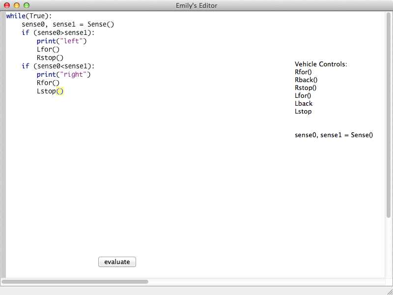
I haven't make applications before, so I'm going in baby steps this week. After looking at the wx python documentation, and Matt's kokopelli source code, I made a very simple application that has an editor window, formatted for python code, and executes the code when you click an OK button. Here's the code, and a picture of it working:
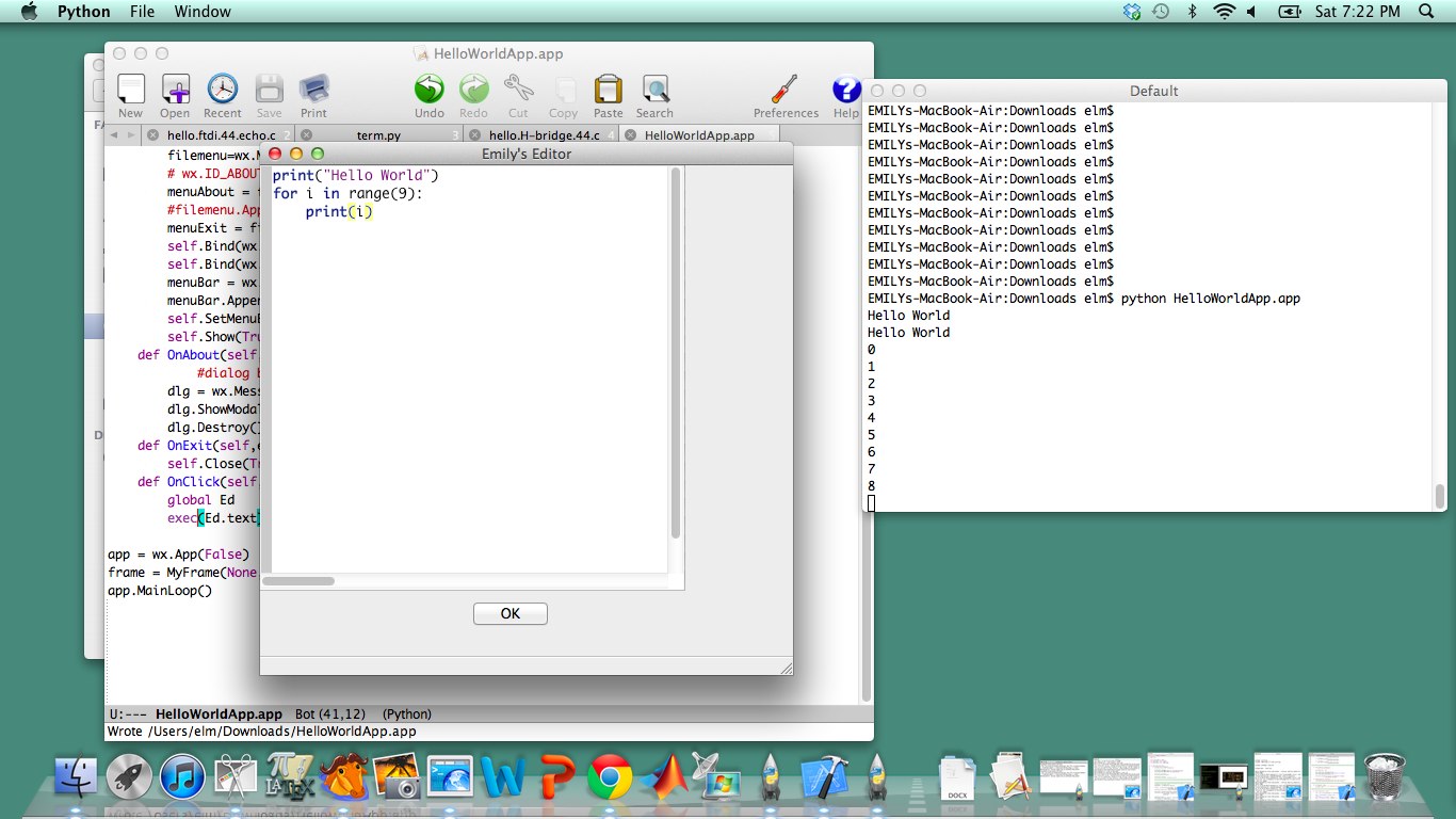
The idea is, connect this with my vehicle, so you can write python code on the computer that controls the vehicle.
I got Python to spin the wheels! The idea is, you can have an editor window in python, and click a button to evaluate the code, and this code controls the serial port, which sends characters to the attiny, which turns the wheels based on that. Here's the .c code and makefile, modified from Neil's, and the Python application, and a picture of it working (you can see the right wheel turning after you click the evaluate button:
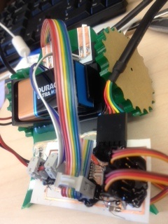
I made a new board, because the first one had the sensors on the PB ports, which have no ADCs. In this board, you need to add a jumper to connect all the grounds. I vinyl-cut it, and just sat it on top of the same vehicle that had the old circuit (At some point I'll need to make a new and sturdier vehicle). Here's the .cad file, and a picture:
It took a while to figure out how do get both inputs and outputs working. I based outputs from the chip on Neil's step response board, which sends '1234' to signal it's about to send data, and I based inputs on Neil's echo board. The main issues I had were solved by A) making sure neither python nor c was waiting indefinitely for an input and B) making sure each correspondence had enough time. I added a lot (100ms) of wait time after having python read inputs. I'm sure I don't need this much time, I just wasn't sure how to make it work consistently with short timelags. I also wound up using the 9600 baud rate instead of 115200, because it was less finicky, but not that I've added a resonator to the chip, I'd like to get the faster baud rate going. I also send a bit from python to the chip every time I read a bit from the chip, so that the chip wouldn't get stuck waiting for an input, and neglect to send outputs. Here's the .c code, makefile, and python application. You can enter code, and it evaluates the code when you press evaluate. The commands to interface with the vehicle are listed on the right of the GUI.
To program the chip with these files, type:
sudo make -f VehicleTxRx.c.make
sudo make -f VehicleTxRx.c.make program-usbtiny-fuses
sudo make -f VehicleTxRx.c.make program-usbtiny
To open the python application, type:
python InputsVehicleBrain.app
Here it is, working with a simple light-following program: