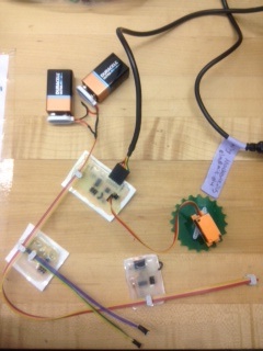
This week, I'm networking multiple boards together, to be sensors and motors for my programmable vehicle. I made boards for one motor, two phototransistors, and an accelerometer, and networked these all together, so each responds to specific commands from the computer. I integrated these with my GUI that I made last week, so that you can enter python code to read from sensors and control motors, and then evaluate the code by clicking a button. The cable connecting the boards brings power, ground, Tx and Rx.
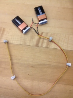
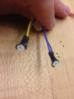
Here are the three boards, battery connector, and phototransistor 'eyes', which I plan to incorporate into my robot.
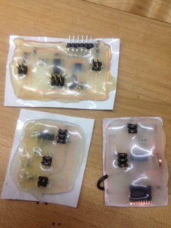
I had some trouble designing the circuits, because I initially misread the MMA1270KEG accelerometer datasheet which calls for extra resistors and capacitors, and a ground plane underneath. But several quick fixes later, my board had a lot more character, and worked as a tilt sensor:
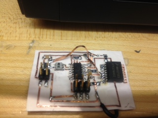
After the corrections, here are the phototransistor, motor and accelerometer .cad files, as the phototransistor, motor and accelerometer .c files and the phototransistor, motor and accelerometer makefiles. To control everything, I used my python app from last week.
There's still a lot left I'd like help on. Python sometimes freezes, if I try to read one sensor immediately after the other, I'm not sure exactly why. I'd like to be able to PWM the motor on the chip (right now I just have forward, reverse and stop, but I'd like to send the chip a speed, and have the motor spin at that speed). My attempts to use interrupts to do this have so far not worked. I'd like to make the robot wireless, so it's less likely to rip itself and the computer controlling it apart. And the robot needs a body.