I made a caliper this week, with a GUI to test how wide it's open. It senses how the step response (a measure of capacitance) changes when copper sheets overlap different amounts.
I started off with Neil's 'step response' board (plus an LED for debugging), and a header attached to paperclips (on the sense and ground pins) which I could clip to different size and shape electrodes. The board sends a step function, and senses voltage at three different delays after the step function. This gives you an idea how the capacitance is changing, because capacitance changes effect the time constant of response.
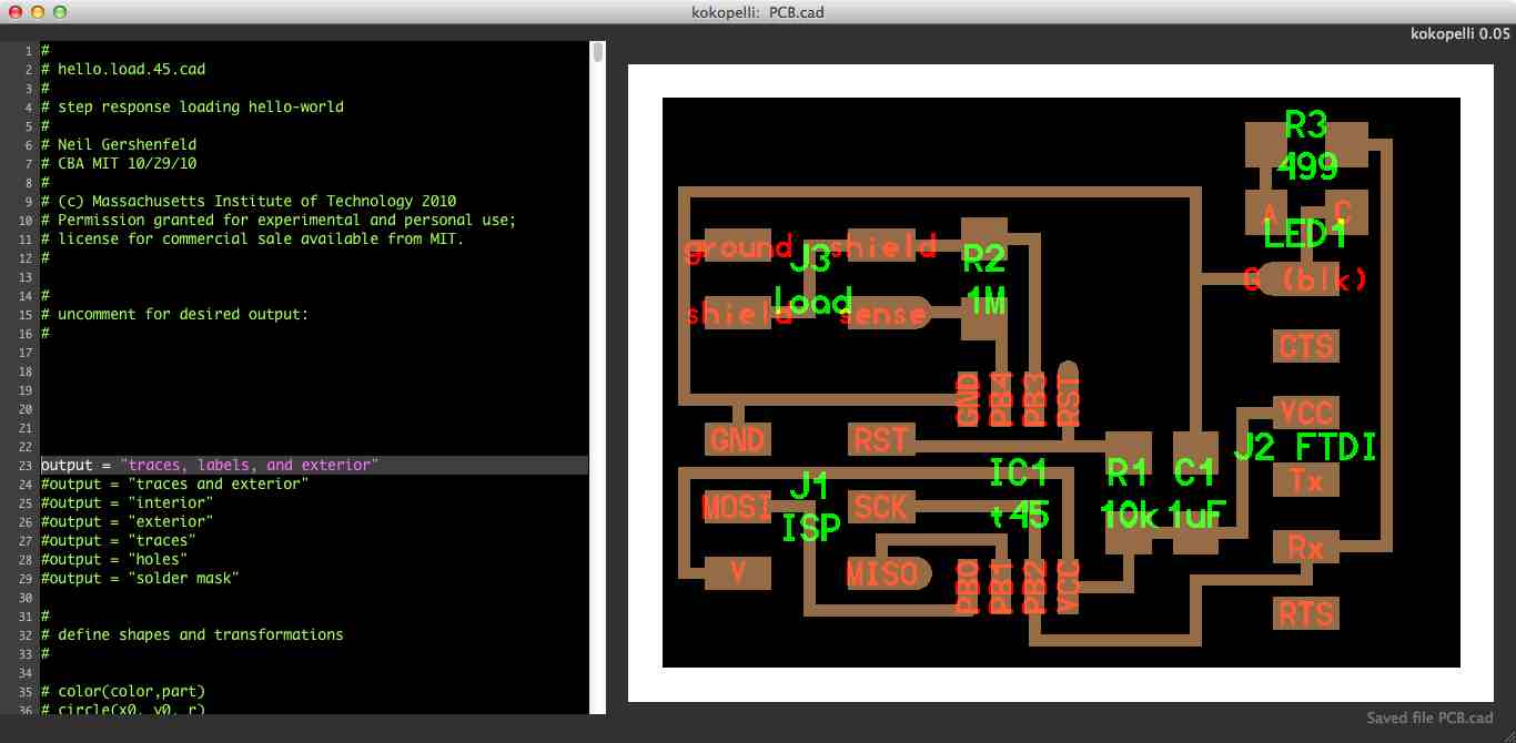
I wanted to add an LED that would mirror whatever the board sent to the computer, just to aid debugging. So I added this to Neil's board in kokopelli. Here's my .cad file, and how it looks in kokopelli:
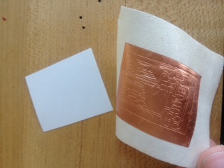
I vinyl-cut the board (it was small and very fast to weed), and covered it with hot glue when I was done for added protection. Previously, I had been using the yellow stickiness-depositing tape instead of masking tape to transfer the circuit, and the masking tape worked much better:
I programmed it according to Neil's step function example, with the .c and .c.make files that are on the class website, and I used Neil's hello.temp.45.py.
How do you get the computer to listen to the chip? I needed to install the FTDI drivers on my mac. I found the name of the serial port by typing ls /dev, and seeing tty.usbserial-FTFBGOT5 in the list of devices. Then, to run the python program through the terminal, I ran:
python hello.load.45.py /dev/tty.usbserial-FTFBGOT5
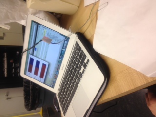
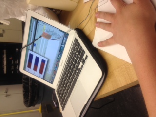
This brought up Neil's GUI:
Matt Keeter helped explain some of the details of Neil's program, and how to do some more things. Specifically:
The canvas commands set up the gui, and tk is the python toolkit that Neil used
To make text to one decimal place that represents the value of a variable called filter1, write"%.1f"%filter1
This is useful for GUIs, and also for saving files. To save a text file from Python, do something like this:
f = open('mydata.txt','w')
f.write('OMG!\n')
f.write('How does this work?\n')
f.close()
To open an application (or do anything else you could do in the terminal) from a python script, do something like this:
import subprocess
subprocess.call(['open', '/Applications/Safari.app/'])
To send emails, consider using Applescript. Through the terminal, you can run applescript with the command
osascript
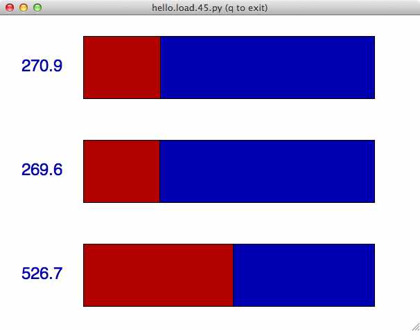
The board can sense when my hand is near it (I've attached "electrodes" (aka vinyl cutter scraps) to paperclips soldered to a header I plugged into the "sense" and "ground" parts of my board). Here are different size bars in the python program for no hand vs hand:
I triggered it to open google chrome when I hovered my hand over the electrode by adding the following line to Neil's python code:
if (filter1<530):
   subprocess.call(['open', '/Applications/Google Chrome.app/'])
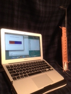
But I wanted to try making traditional measurements, and also I've been meaning to try acrylic on the laser cutter, so I'd like to make a caliper that uses capacitive sensors. It probably won't be that accurate a caliper, but it'll be a fun exercise in using capacitive sensing. Here's the caliper I designed in Kokopelli:
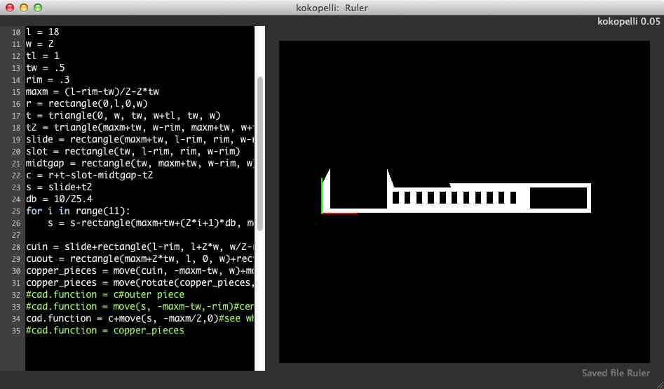
Here is the .cad file.
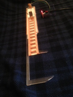
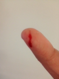
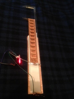
I cut the caliper out of .25in clear acrylic on the laser cutter, using Charles' suggested settings: 20%Speed/100% power for cutting 1/4'' acrylic and 35%speed/100%power for 1/8'' acrylic. I cut the copper plates on the vinyl cutter, and stuck them onto each piece of the caliper, separated by insulating vinyl. This way, capacitance will change when the caliper opens and closes as more or less of the two copper sheets will overlap. Other than getting a copper papercut, assembly went smoothly:
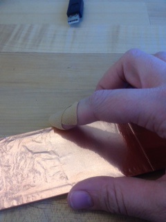
I wound up with some neat-looking acrylic 'ice cubes':

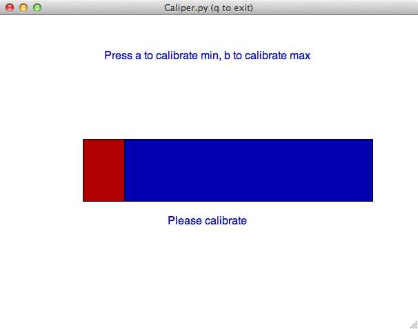
I modified Neil's code to make a .py file that I could calibrate to capture the full dynamic range of my caliper. The GUI instructs you to move to the minimum and maximum values you want to measure, and press a and b respectively. After it's calibrated, the bar and text in the GUI reflect relative distance.
Calibrating:
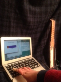
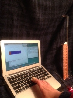
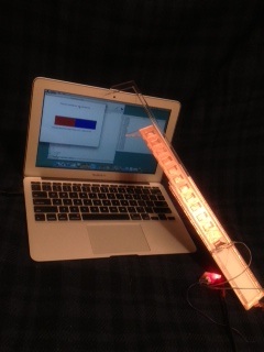
Making measurements:
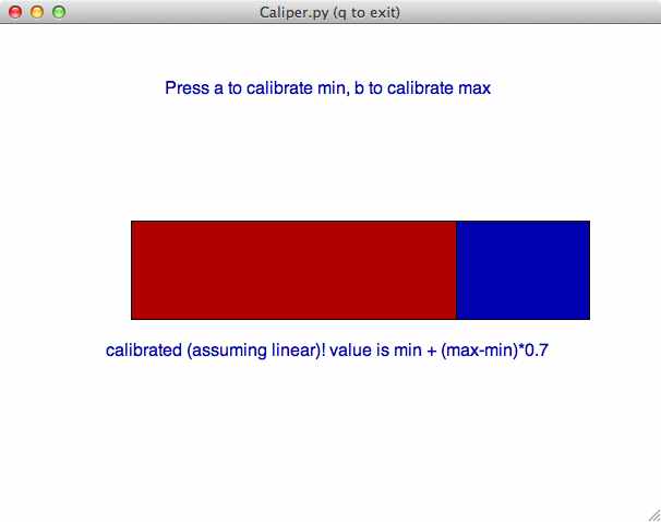
Now I have a calibrated capacitive caliper -- perhaps alliteration was my goal all along. It qualitatively follows the distance between the caliper probes, but it's not very well calibrated. The python code assumes linearity even though the relationship between the step response and capacitance is not linear but instead includes an exponent as the capacitor charges. A more accurate capacitive caliper would take this nonlinear relationship into account, and would also include better sheilding. For now, though, I'm stuck with a qualitatively calibrated capacitive caliper. I'm pretty happy with the project, because I learned a lot (step response, python interfaces with serial ports and guis, acrylic on the laser cutter), and got more practice with coding and with electronics production. Also, I'm happy about the election!

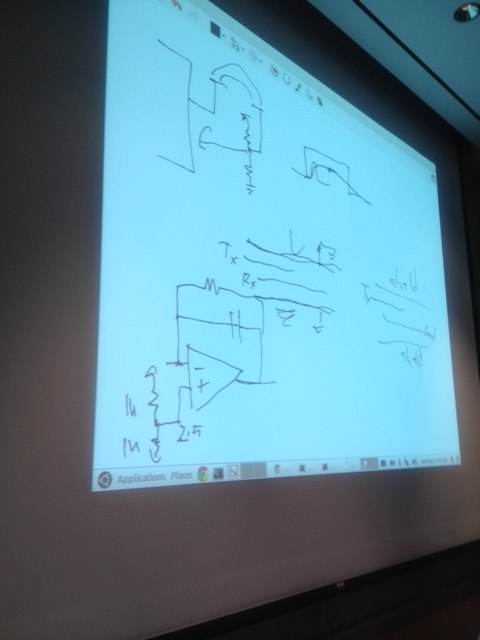
In class, Neil had some suggestions that would make the caliper much better. First, I can integrate the signal (with an opamp and capacitor), so that it varies linearly with capacitance. Second, I should sheild everything, so that measurements don't change based on how you're holding the caliper, or what surface it's near. The Tx-Rx board (instead of the step response board) is probably the best way to do this. Here are Neil's notes from class on how to implement this: