Week 5: Electronics Design
This week for HTM(A)A, the mission was to recreate a circuit and then modify that circuit by adding at the least, an led and button . Since I was not familiar with circuitry, I decided to stick to the minimum. BUT! I did make it as small as I could, as well as add an unsure-if-this-is-gonna-work face on it. boom.
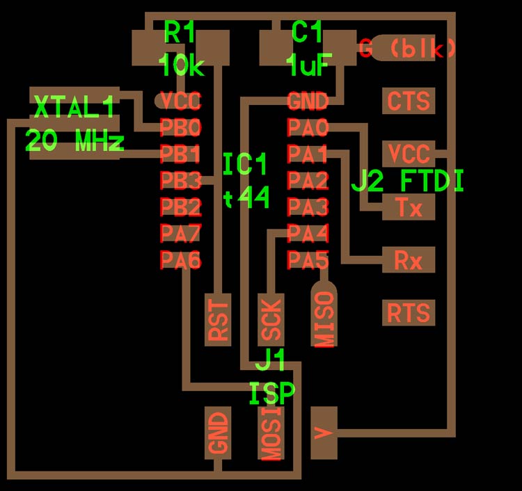
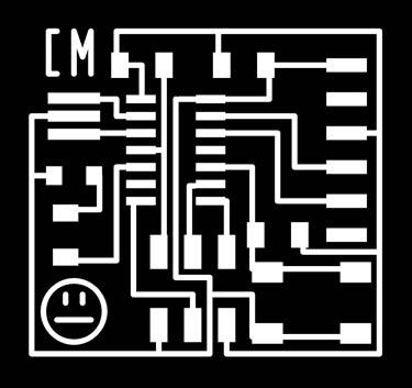
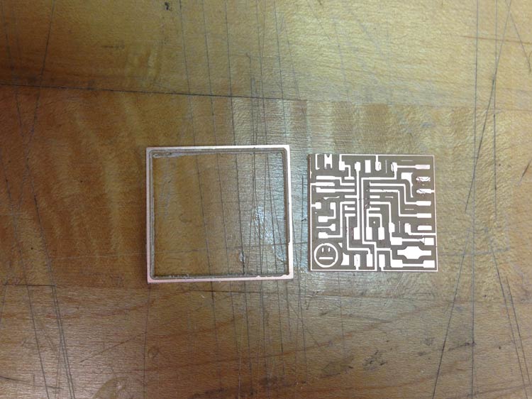
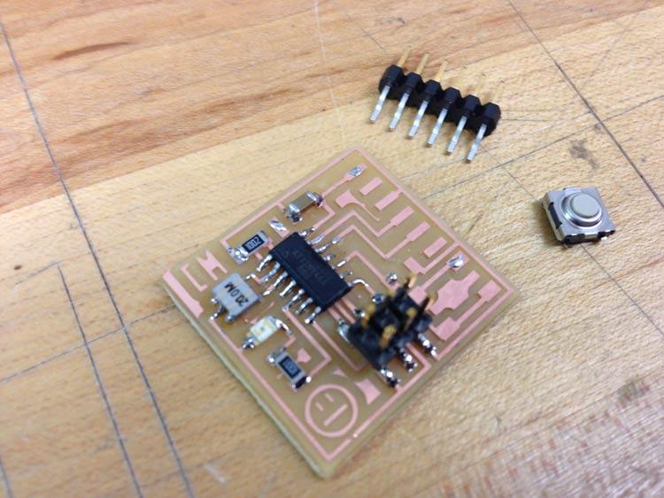
Above is the board we had to replicate. In order to do so, we had to create a schematic, then draw the real traces on a board layout, save it as a black-and-white png for the Modela. he software we used was Eagle PCB-Software.
By loading component libraries in Eagle, you can easily layout your board with the right pad sizes and spacing! The two libraries used for this board were fab.lbr and SparkFun.lbr.
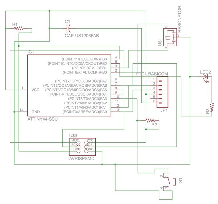
Eagle basically has two modes...schematic mode and board mode (kind of like drawing mode and paperspace in autoCAD). Schematic is for laying out the logic, and the other (Board) is for physical printable connections. When you start a new project, you have to create these at the same time so they become synchronized. This is the schematic I created in Eagle.
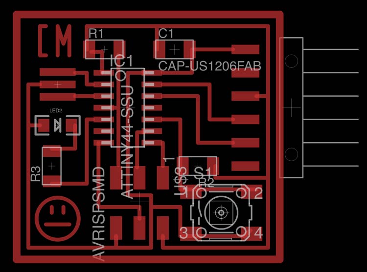
This is my design in board mode. Note face and initials. For line Thickness I used the following:
Line thicknesses
- Traces: 0.016 in
- Outline: 0.032 in
For the grid snap I first started out using .025 in as an increment but found that for the closest traces, I needed .015.

Here's what the exported pngs look like. I exported these as Monochrome at 1500 dpi
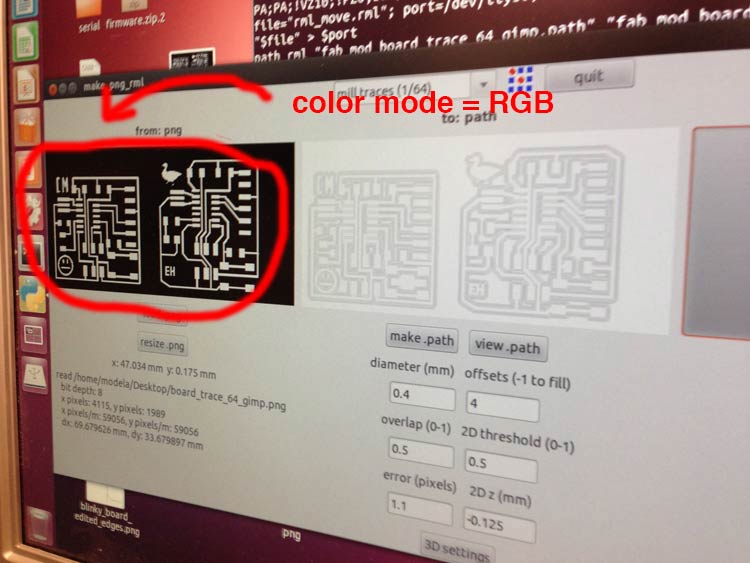
Time to send to fab modules! Me and Seto conserved energy by pairing our boards up. We found that we kept getting this strange error when trying to load our png. It was something like:
Cannot convert String to Float.
We found that once we changed the color mode of the png from INDEXED to RGB, it worked fine!
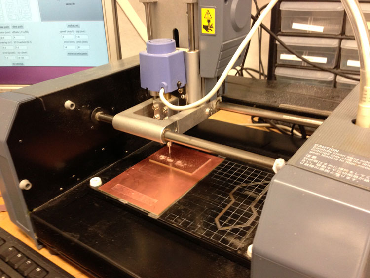
Let the milling begin! We found that near the origin, the bed seemed to be not even, so our first try kind of failed. Placing the board in the back on the second try helped correct this.
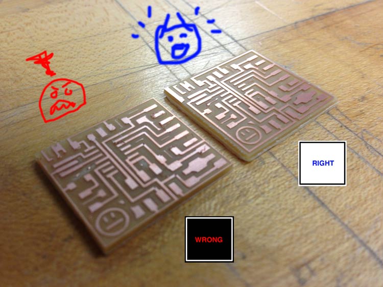
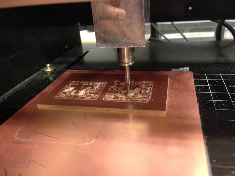
Uh oh. Looks like I cut too far into the board!! Why? Well thats because I forgot to invert the outline png, so it was cutting the inside of the edge, vs. the outside. A very stupid mistake, but oh well.. the second time I got it right.
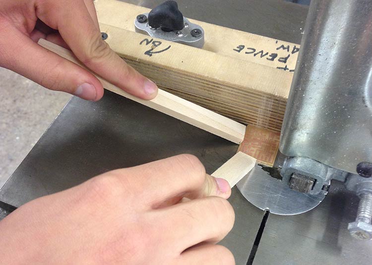
Also, on the second pass it seemed that the outline cut (done at -1.65) was not enough this round. Why? No idea. Had to resort to the bandsaw to salvage this guy. Worked fine
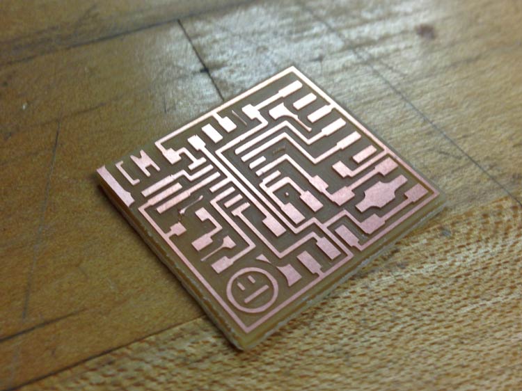
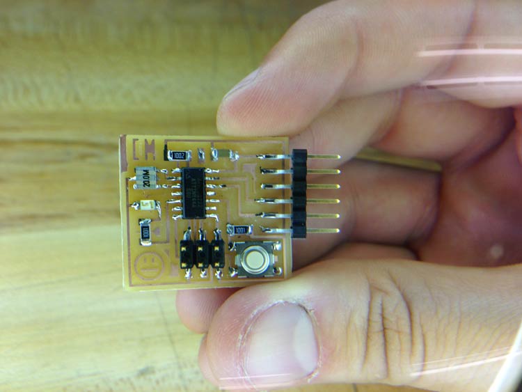
Stuffing the board! No problems here (that I know of, at least).
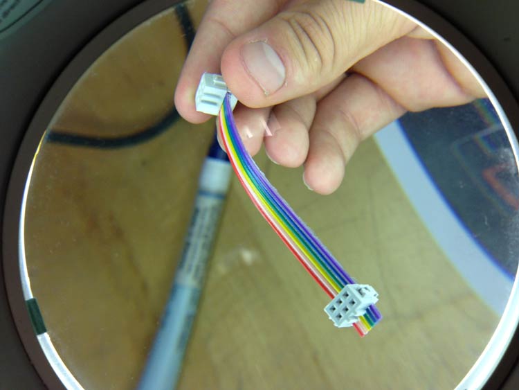
Made my own cable! To do so, you use the 9-cable rainbow strip...and take 3 colors off to make it 6. Then use 2 6-pin cable heads to pierce both sides. done, easy!
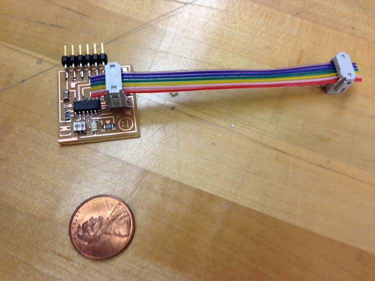
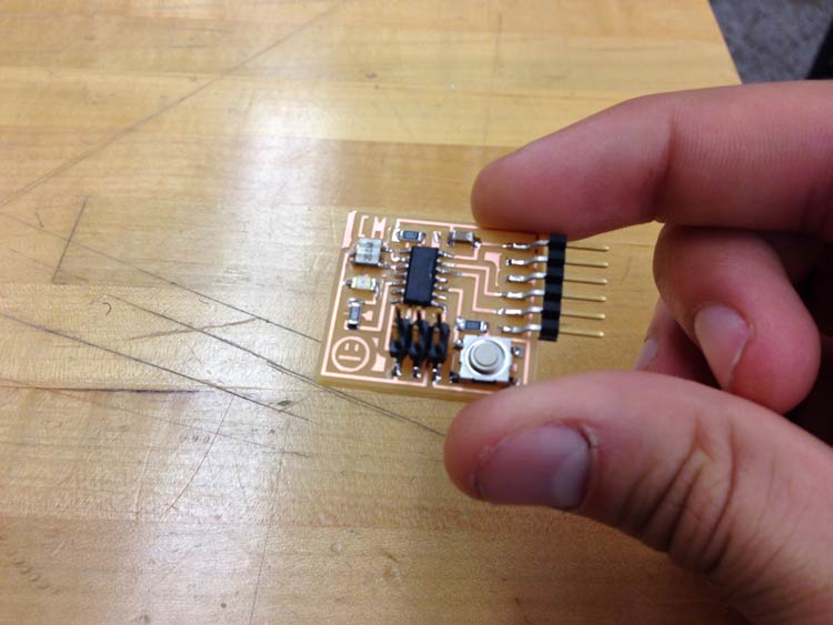
Ready to be programmed, but first, The infamous penny comparison. Yes this little guy is small.
What to Improve
- I could be a little more creative with my circuit, but for now, I'm playing it safe.
- I should leave a little bit of room for the FTDI to rest on, totally forgot about that.
- I would like to get the board outline cut all the way through next time
Tips
- For the PNGs, make sure RGB is the color mode (not Indexed) in Gimp or Photoshop.
- Also make sure your PNG outline is inverted after exporting from eagle.