A GUI ACTIVATED LED INTERFACE
|
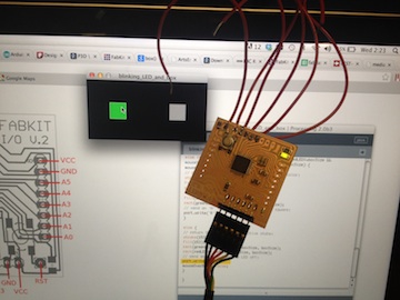 |
This week was one of those moments - getting my LED to blink when I did something in my handcrafted GUI!! And I did it in the IDE which I really find most effective and intuitive - I've found my language. Hello Arduino and Processing. And therefore Hello Fabduino.
HOW TO MAKE A GUI WHICH CONNECTS TO YOUR HARDWARE
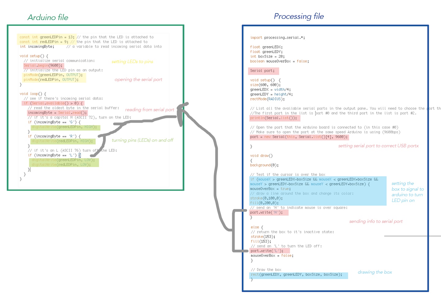
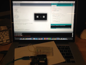
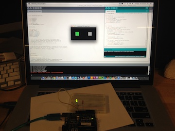
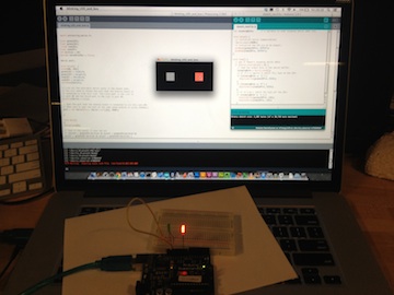
1: FIND AN EXAMPLE IN THE EXTENSIVE ARDUINO AND PROCESSING FORUMS The Physical Pixels example on the Arduino website is a great starter to help you understand how to activate your hardware via a GUI. In this example a simple button designed in Processing turns an LED on or off when the mouse hovers over it. I edited it to include another button and LED. |
|
|
|
2: TEST IT USING AN EXISTING ARDUINO
|
|
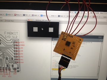
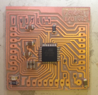
3: MAKE YOUR OWN FABDUINO As I'm definitely an Arduino/Processing fan, I made my own Fabduino using Tiffany's great page to take me through the process step by step. It's a very fiddly board, so I also utilized the microscope, solder paste and heat bed PCB assembly workprocess to make sure that the board didn't have any shorts and worked properly first time - which it did! |
|
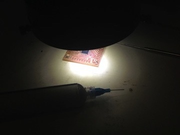
Using solder paste to load all the pads on the traces and then the microscope to position the components on the solder pasted traces
|
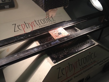
Put the pasted and positioned componented board onto the heat bed, heat it up and then move the gantry over the components to weld the components to the board
|
 |
4: BURN THE BOOTLOADER ONTO THE FABDUINO USING YOUR FABISP
|
