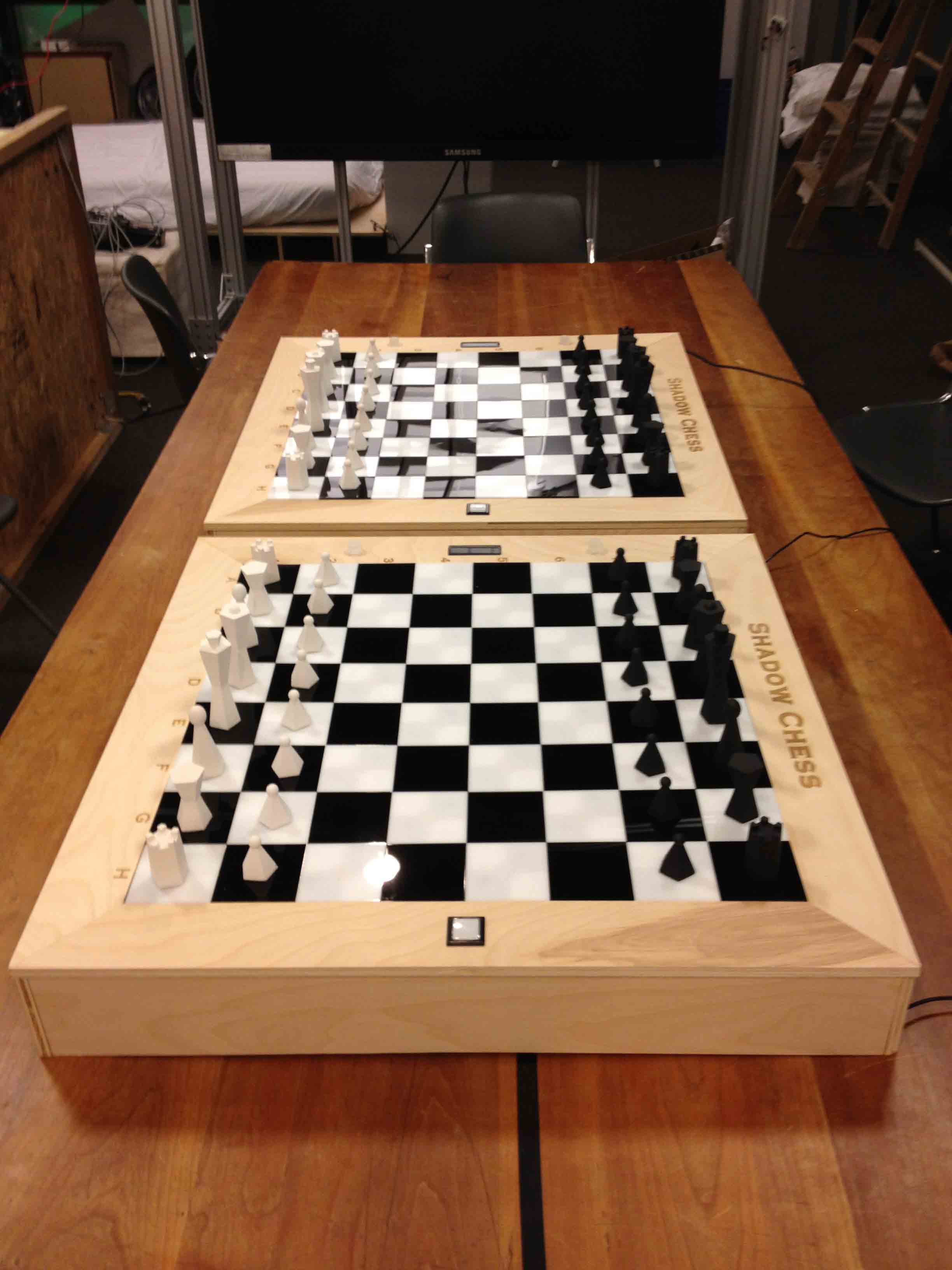
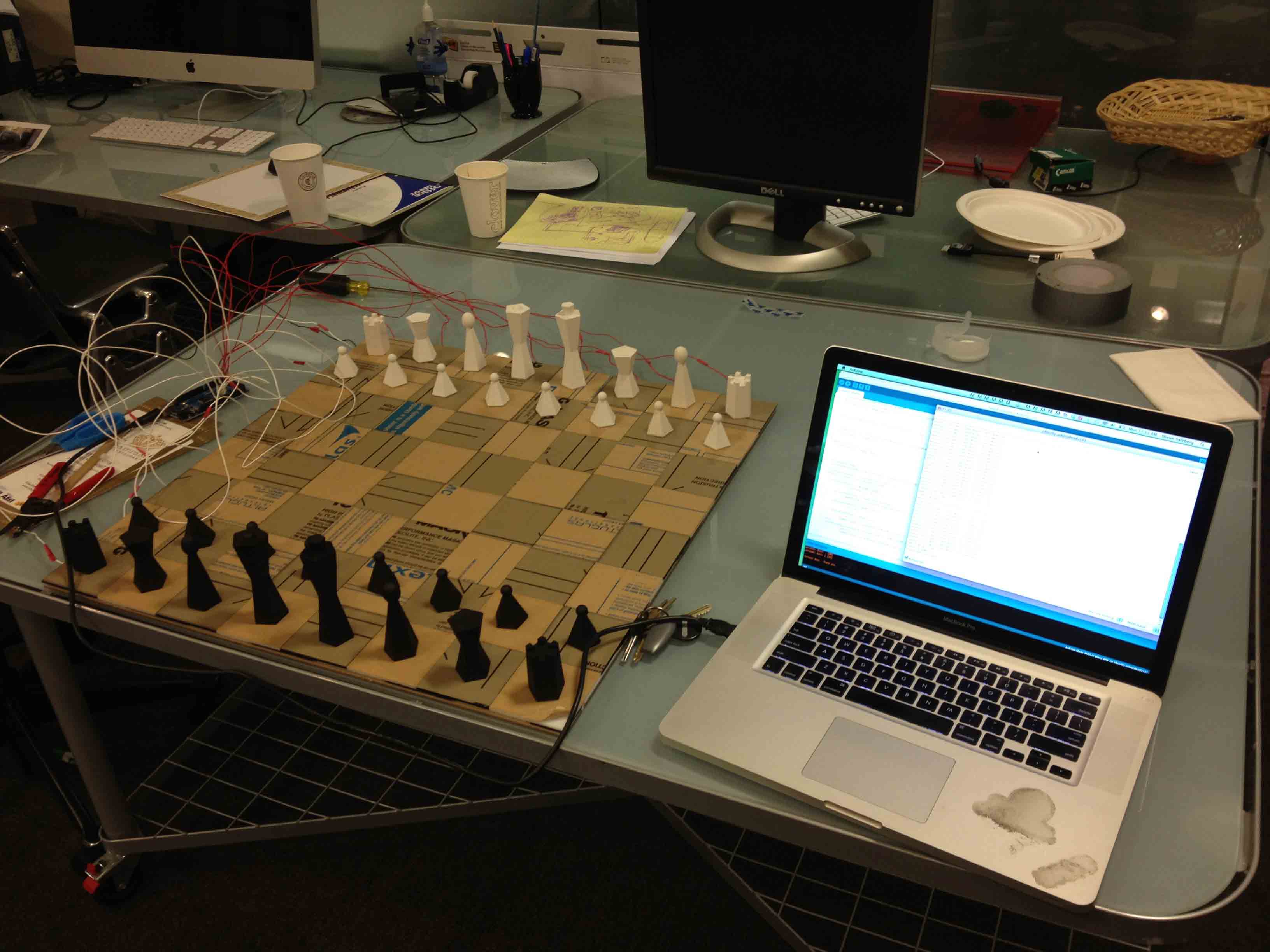
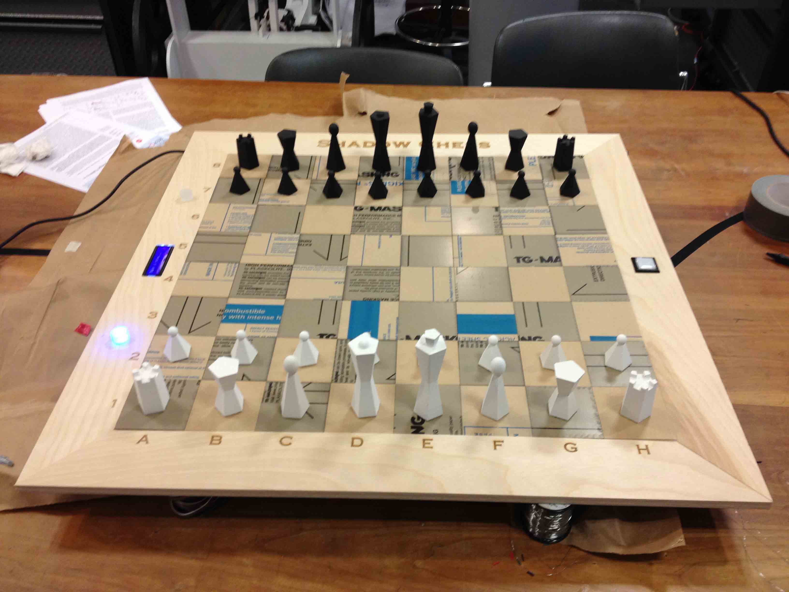
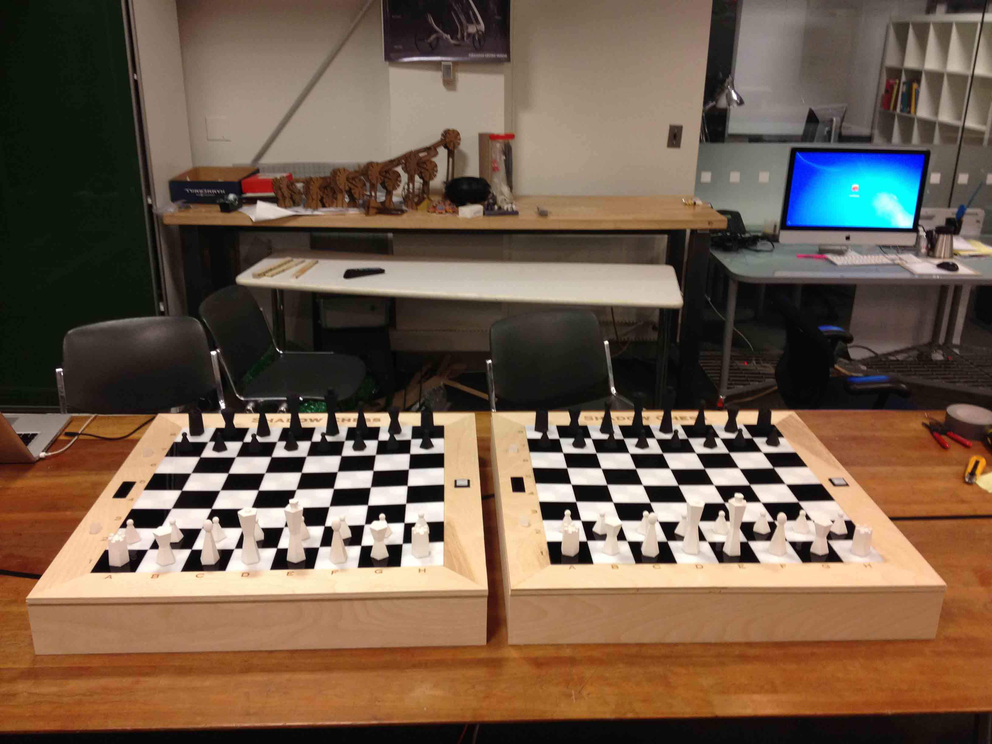
For my final project in How To Make Almost Anything, I designed and built a pair of internet-connected chess sets, which I've dubbed, "Shadow Chess". The boards let you play a real game of chess with a remote opponent. When you move a piece on one board, it senses where it was moved to and relays that information via wifi to the second board, which then "shadows" it by physically moving the piece to the appropriate square using magnets. I made the pieces, board, enclosure, machine, and a portion of the electronics from scratch.
Making the Pieces
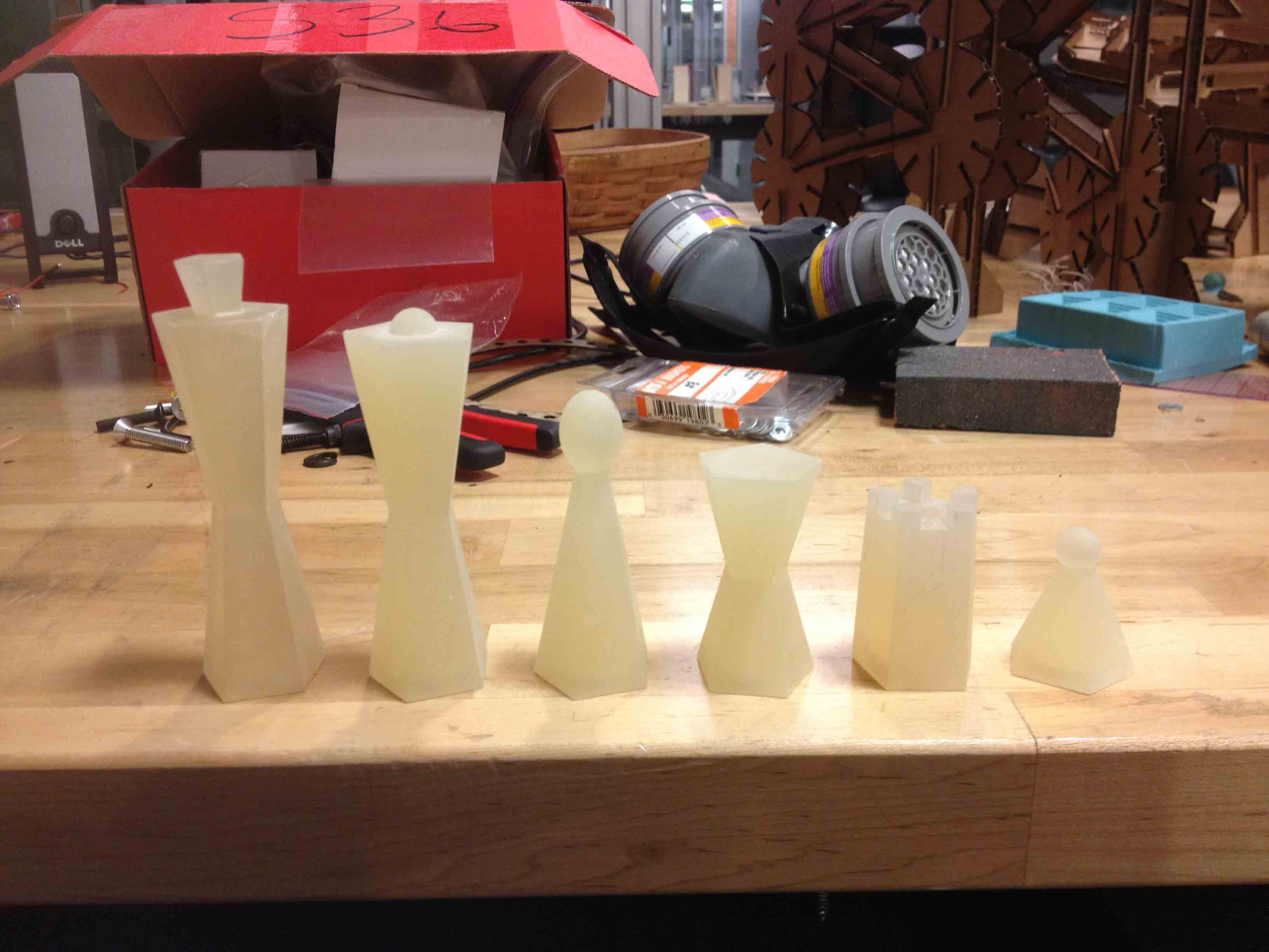
As described in week 3, I designed the chess pieces parametrically using Grasshopper a few weeks ago.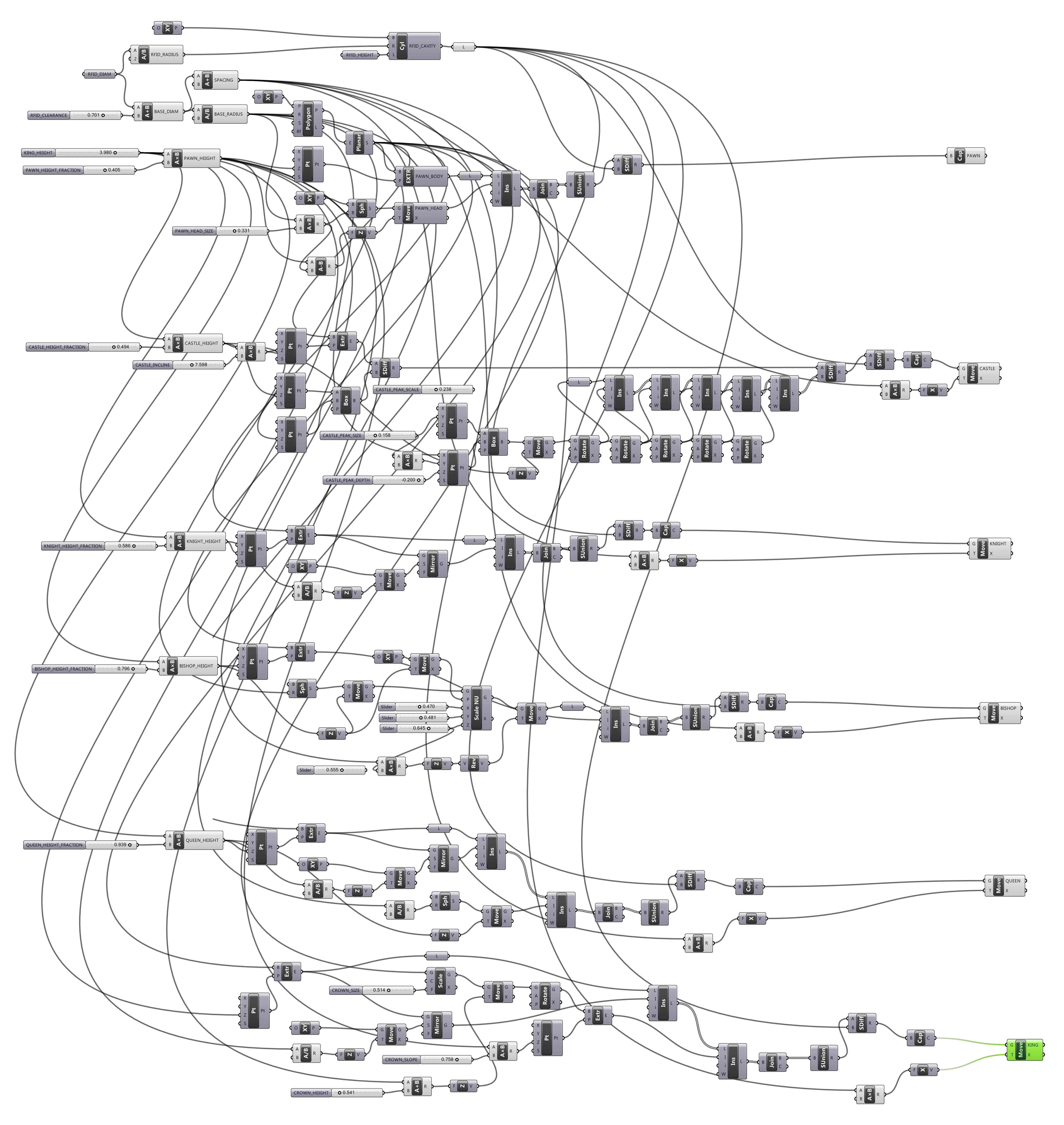
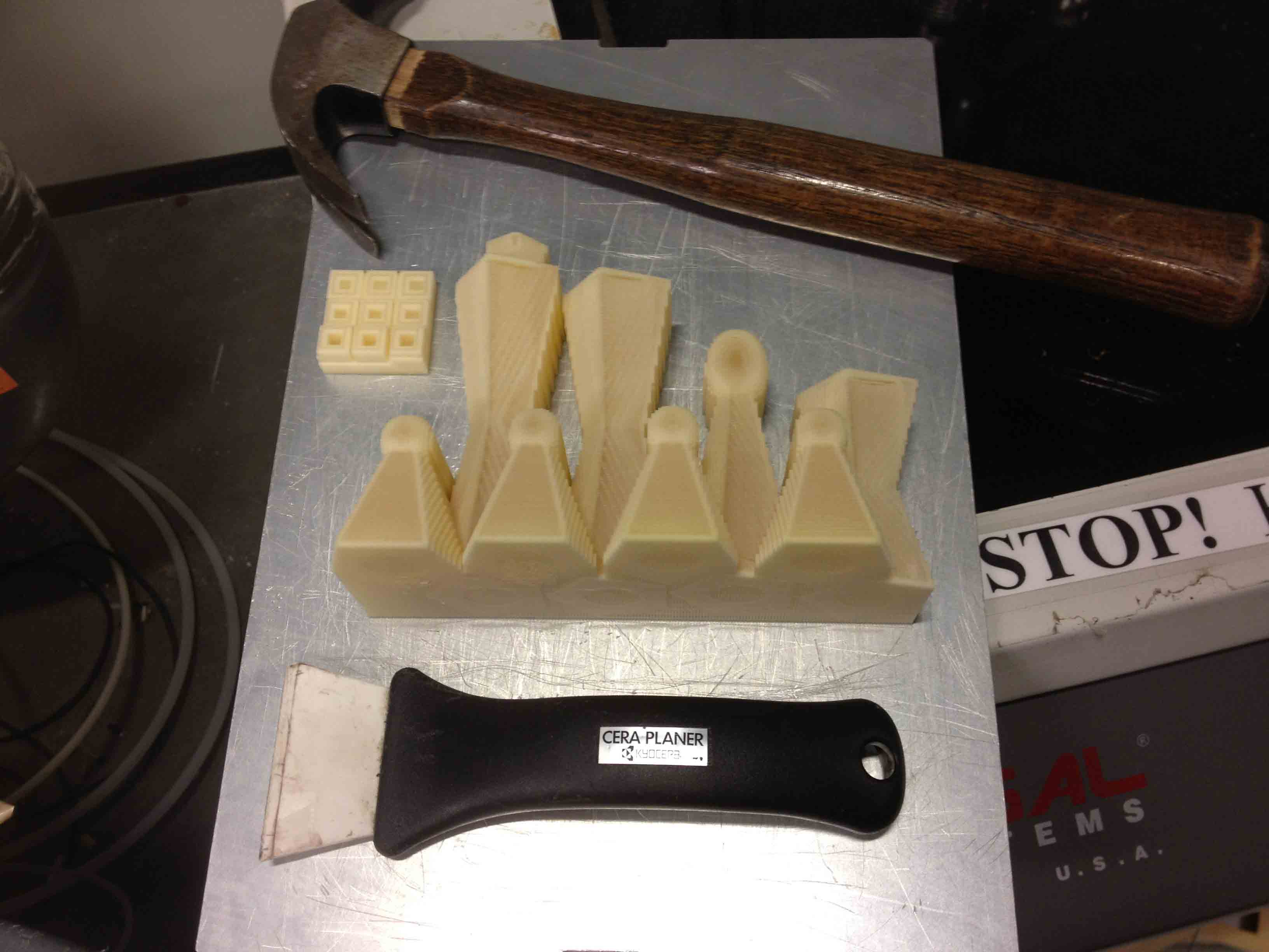
More recently, I 3D printed them all so that I could make molds out of them, since 3D printing all 64 pieces would have been time and cost prohibitive.
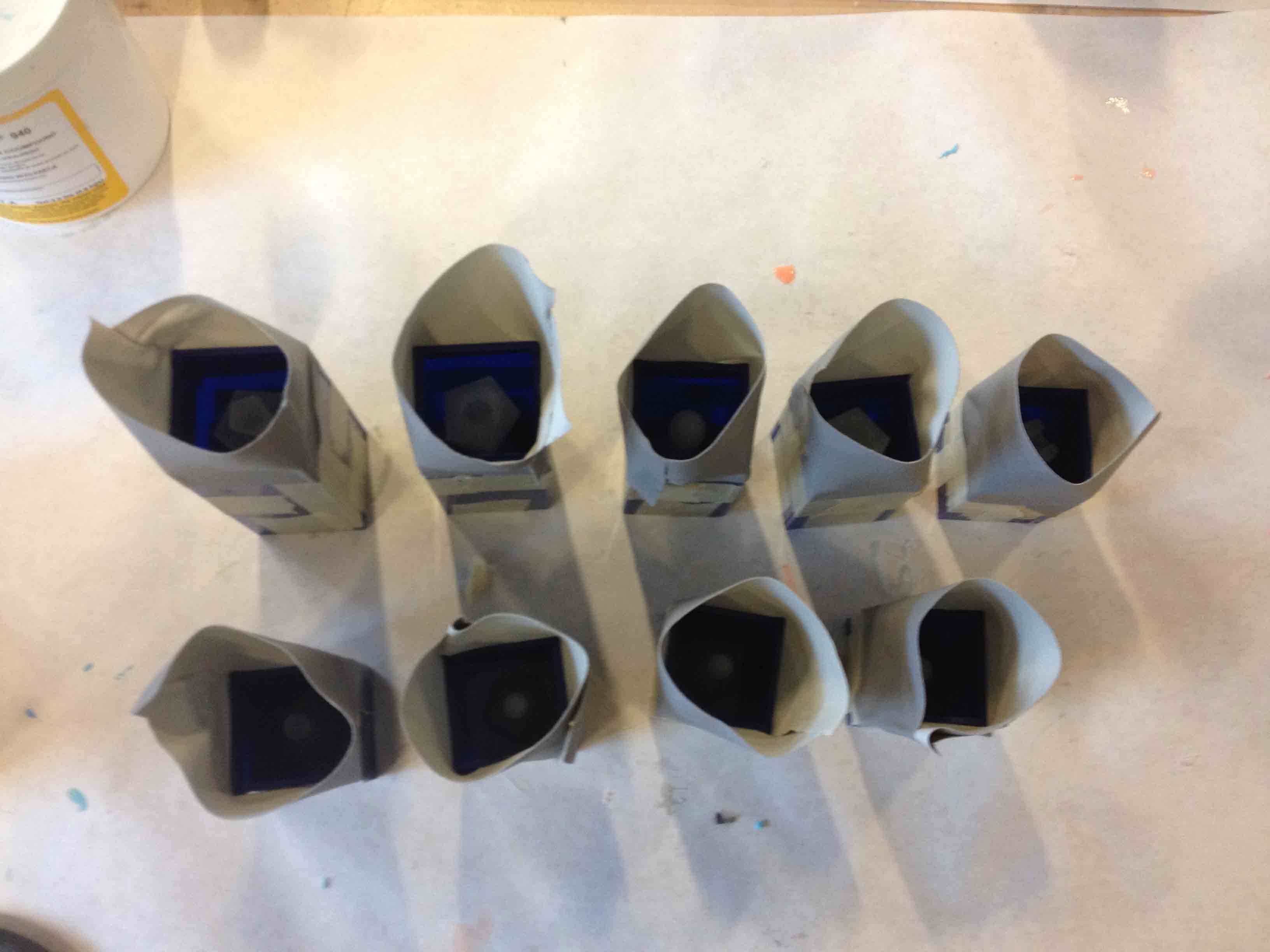
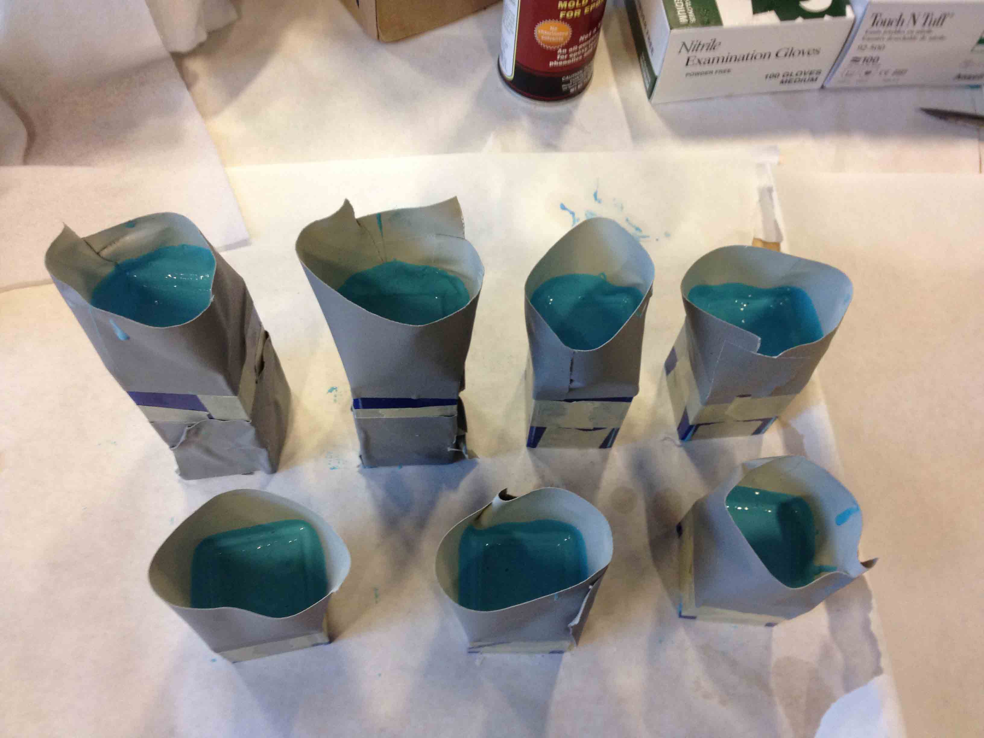
I laser-cut boxes to fit them into, glued the pieces to the bottoms to keep them still while molding, added duct-tape walls to the tops to catch overflow, then poured in some OOMOO silicon to make molds of the pieces.
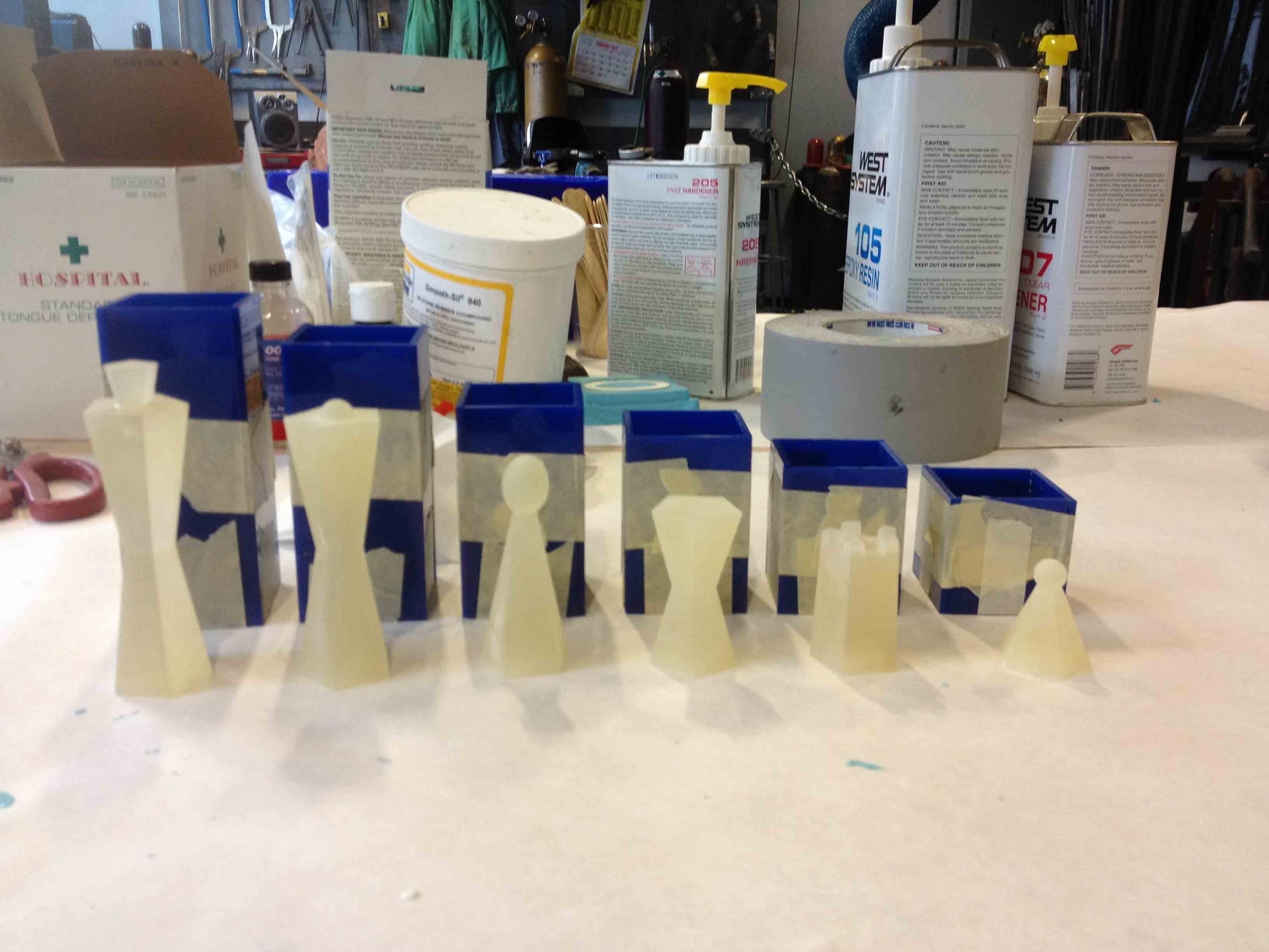
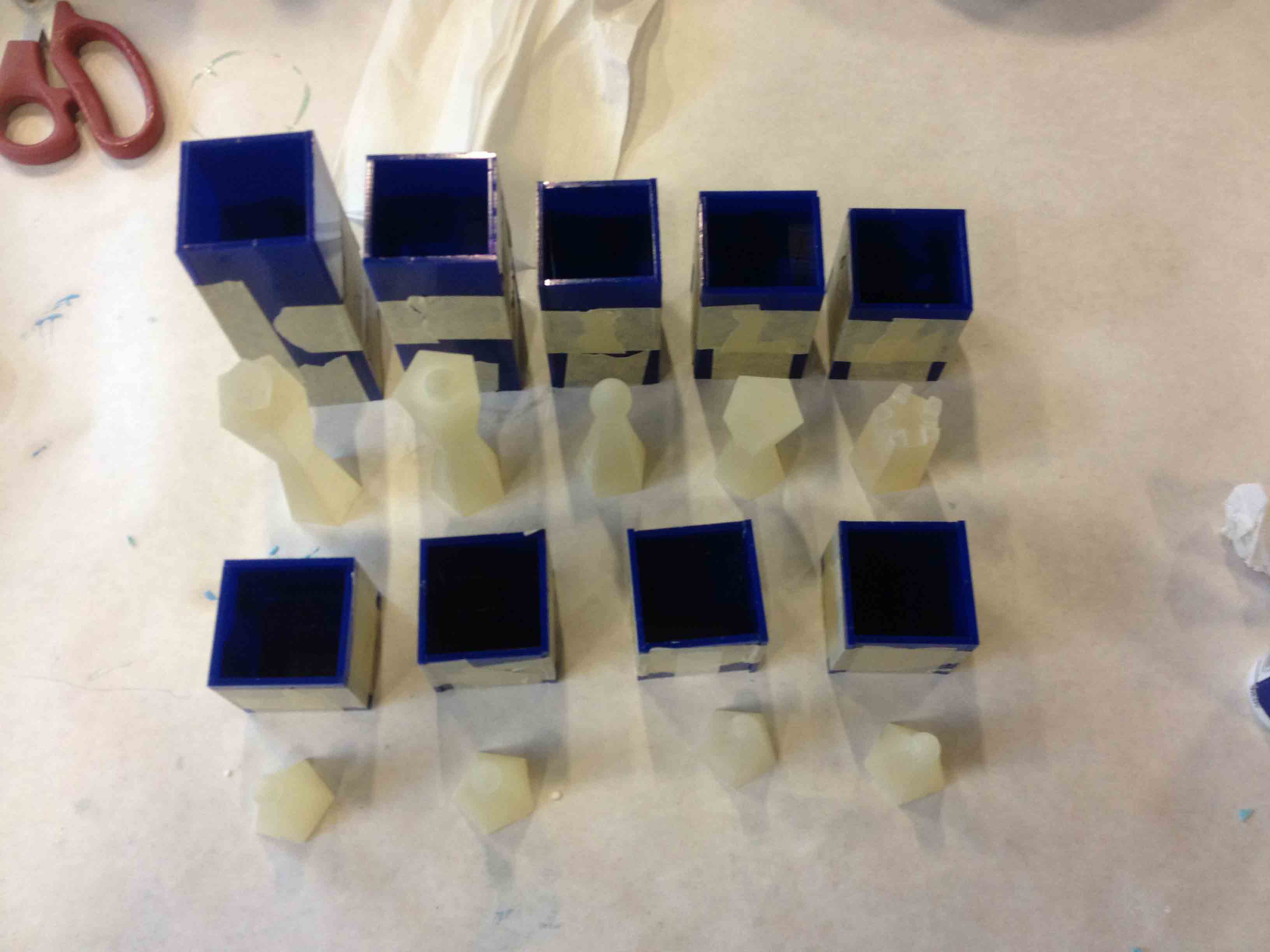
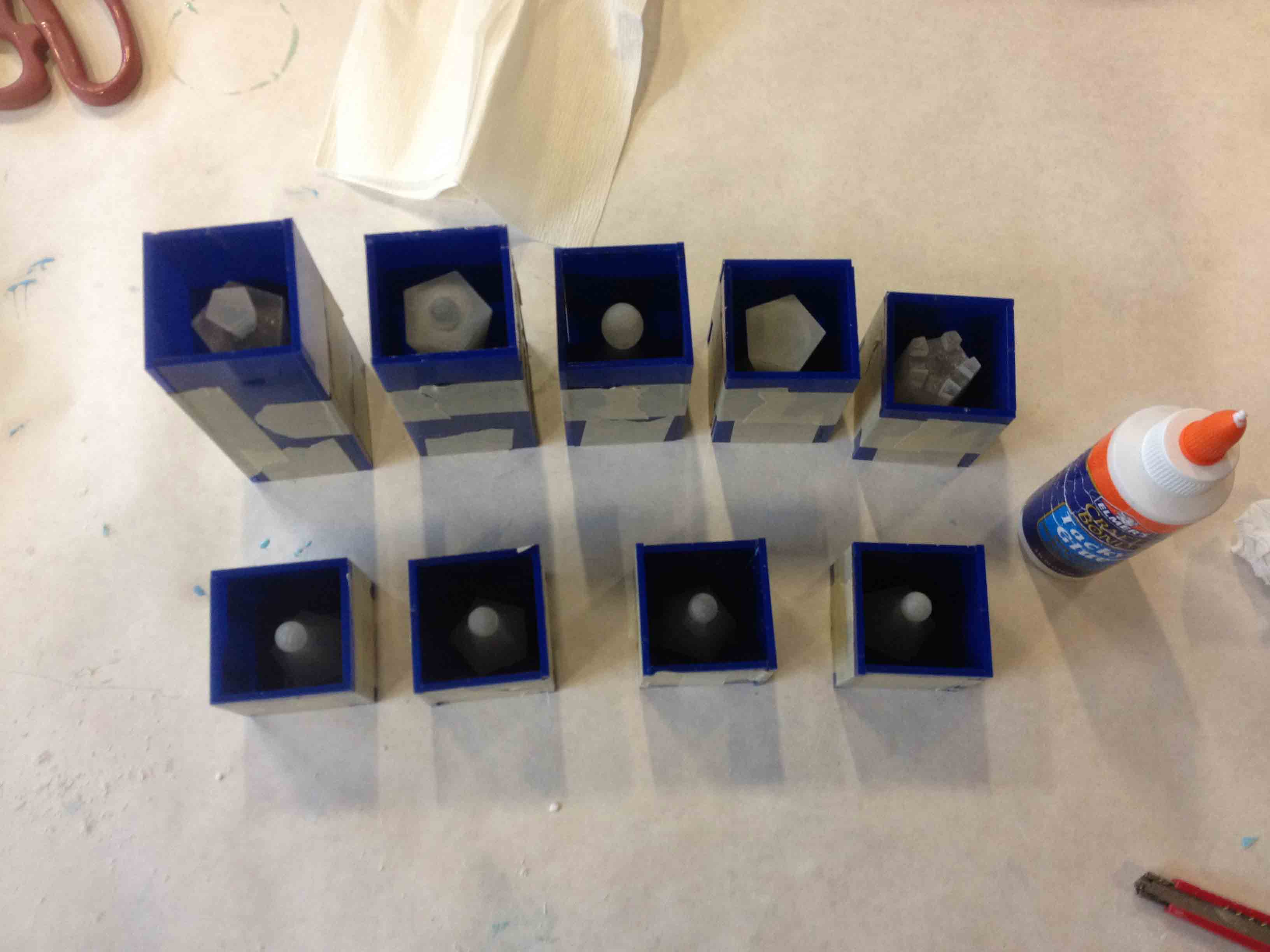
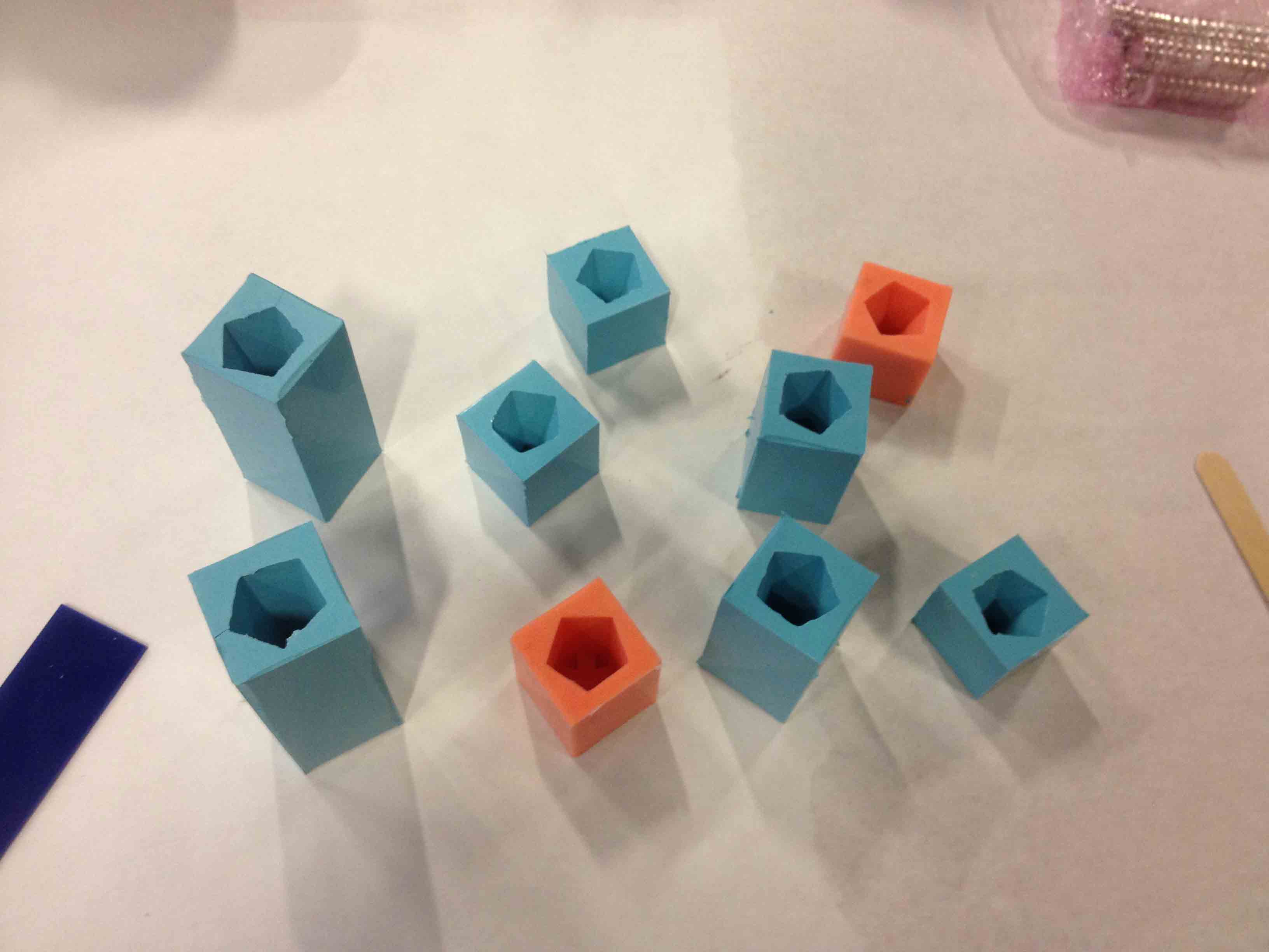
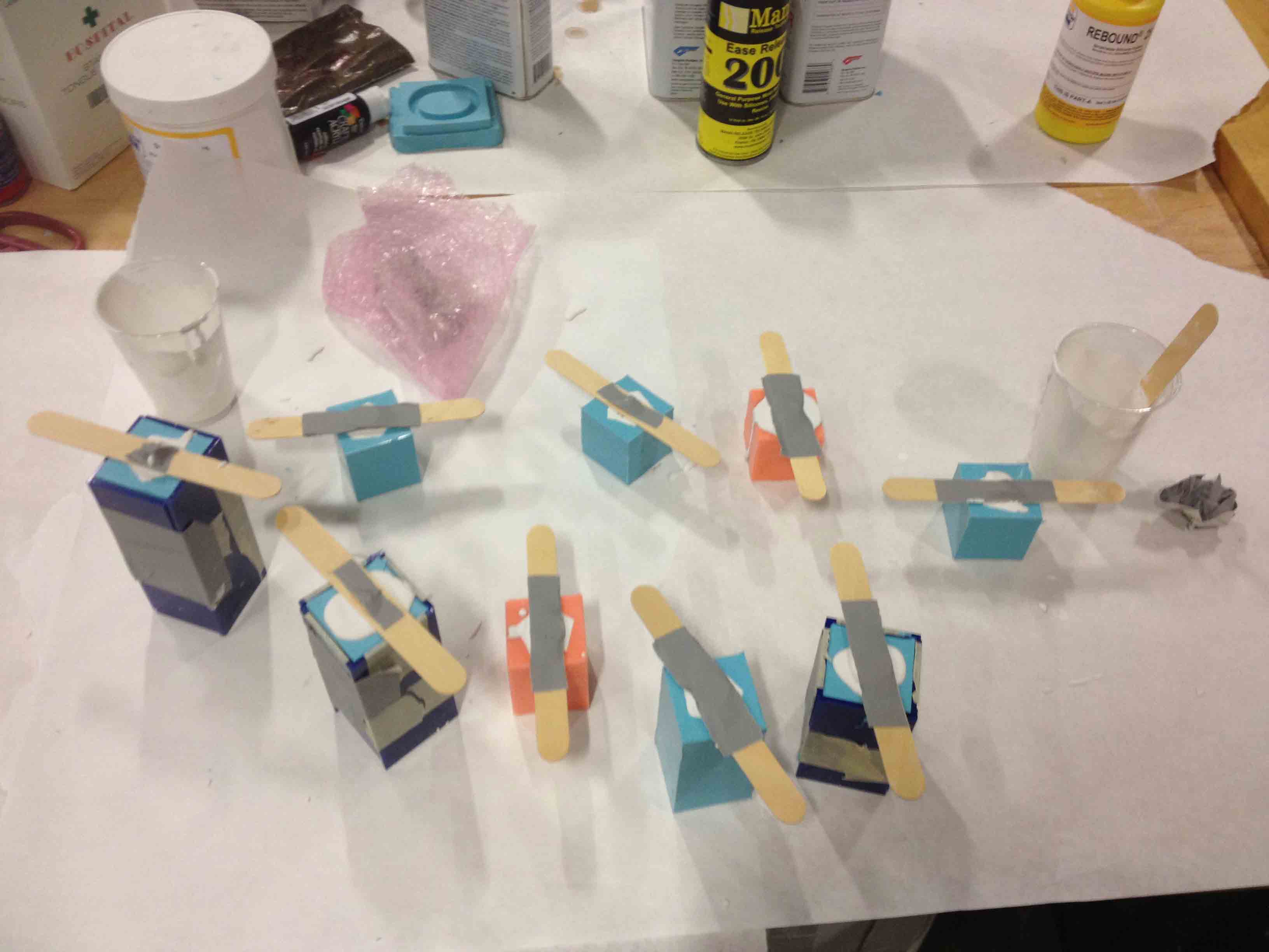
I made one mold for each piece, with the exception of the pawn, for which I made four molds (so that casting the 32 pawns later would go more quickly). I cast all 64 pieces using drystone, and embedded magnets directly into the bottoms of the pieces, using popsicle sticks to hold them in place while casting. I was careful to make sure all the magnets were aligned in the same way so that the magnetic actuator I would later build would work properly.
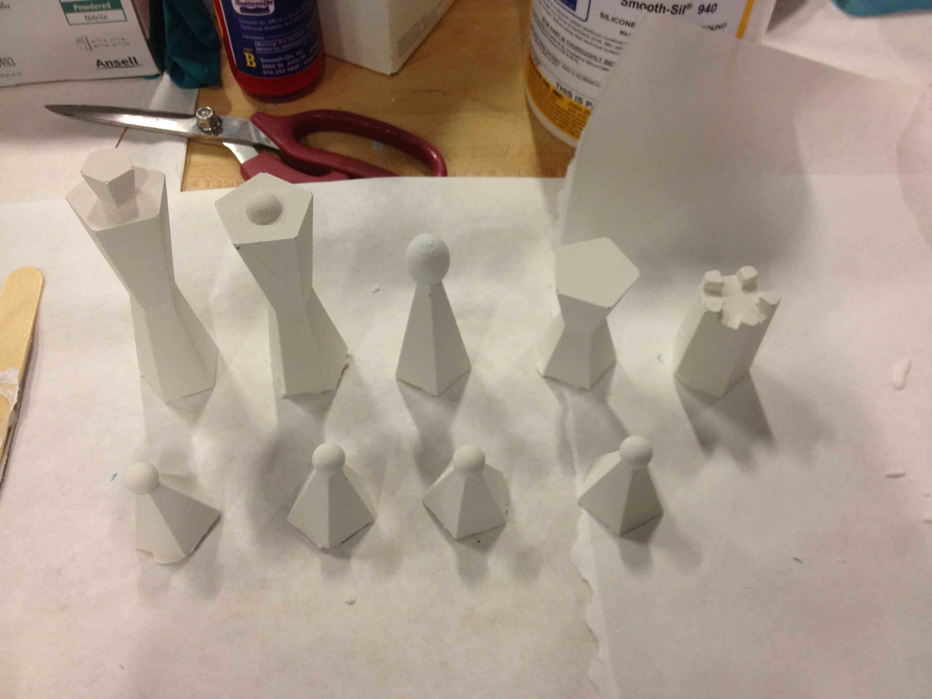
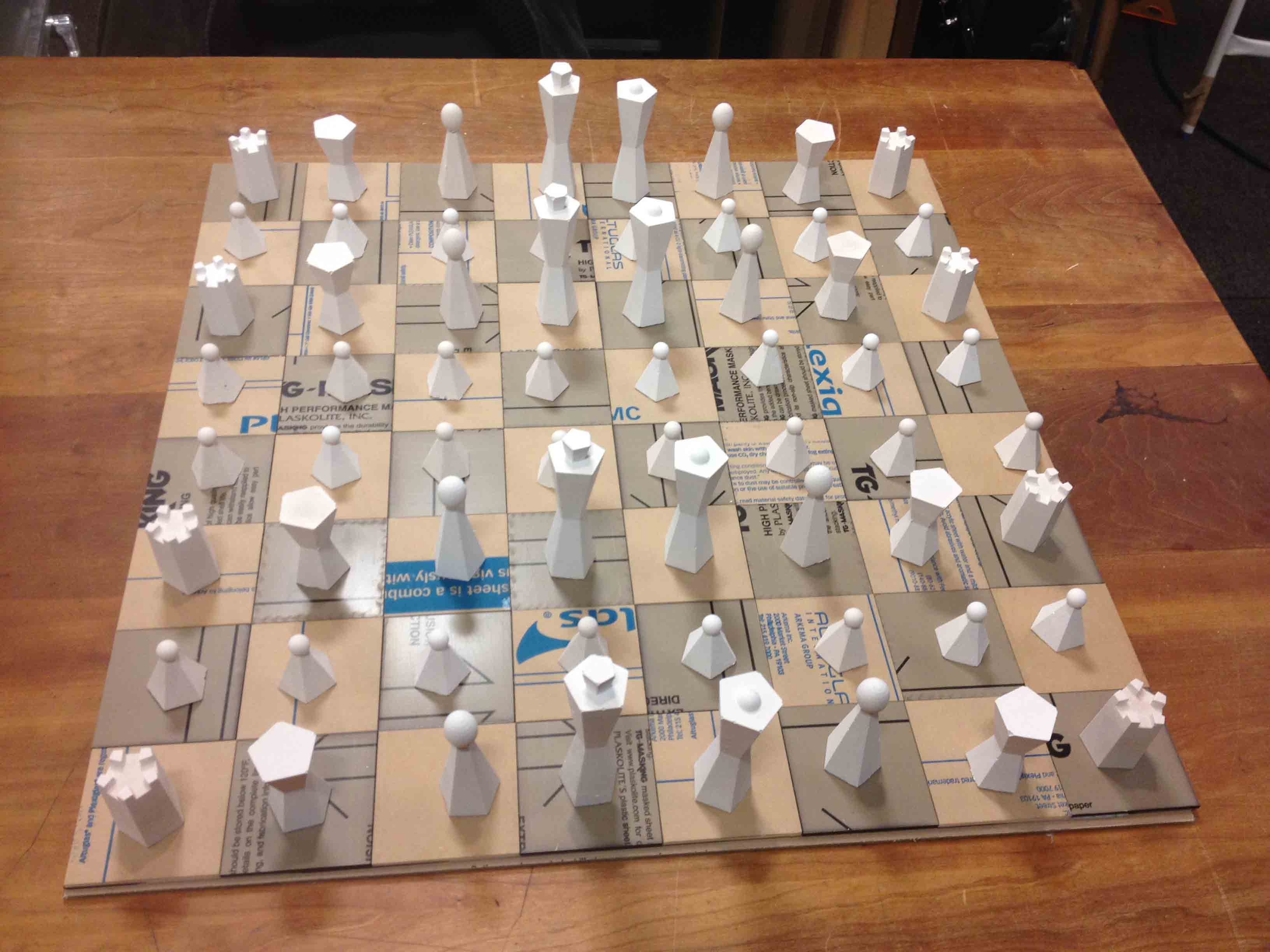
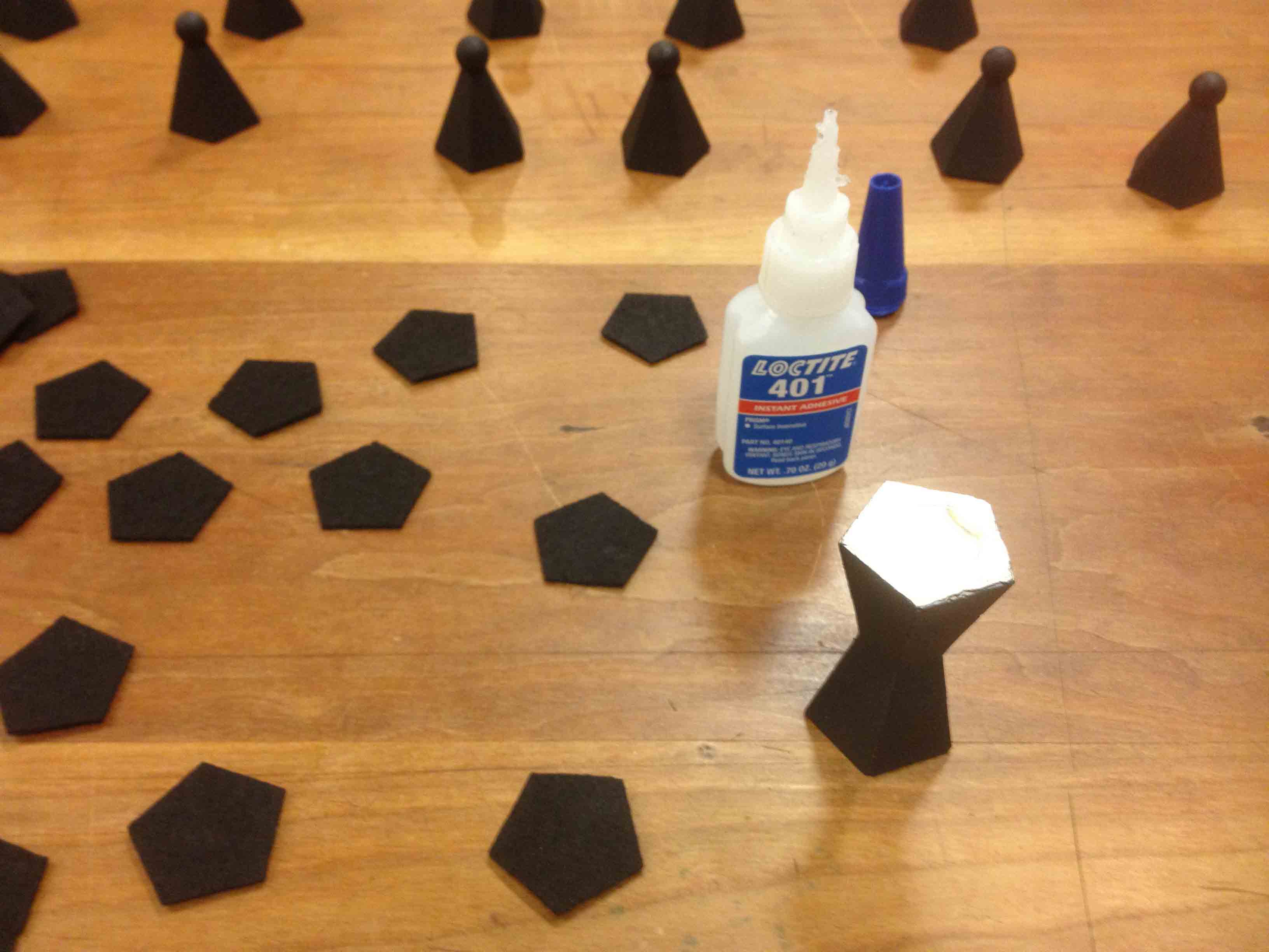
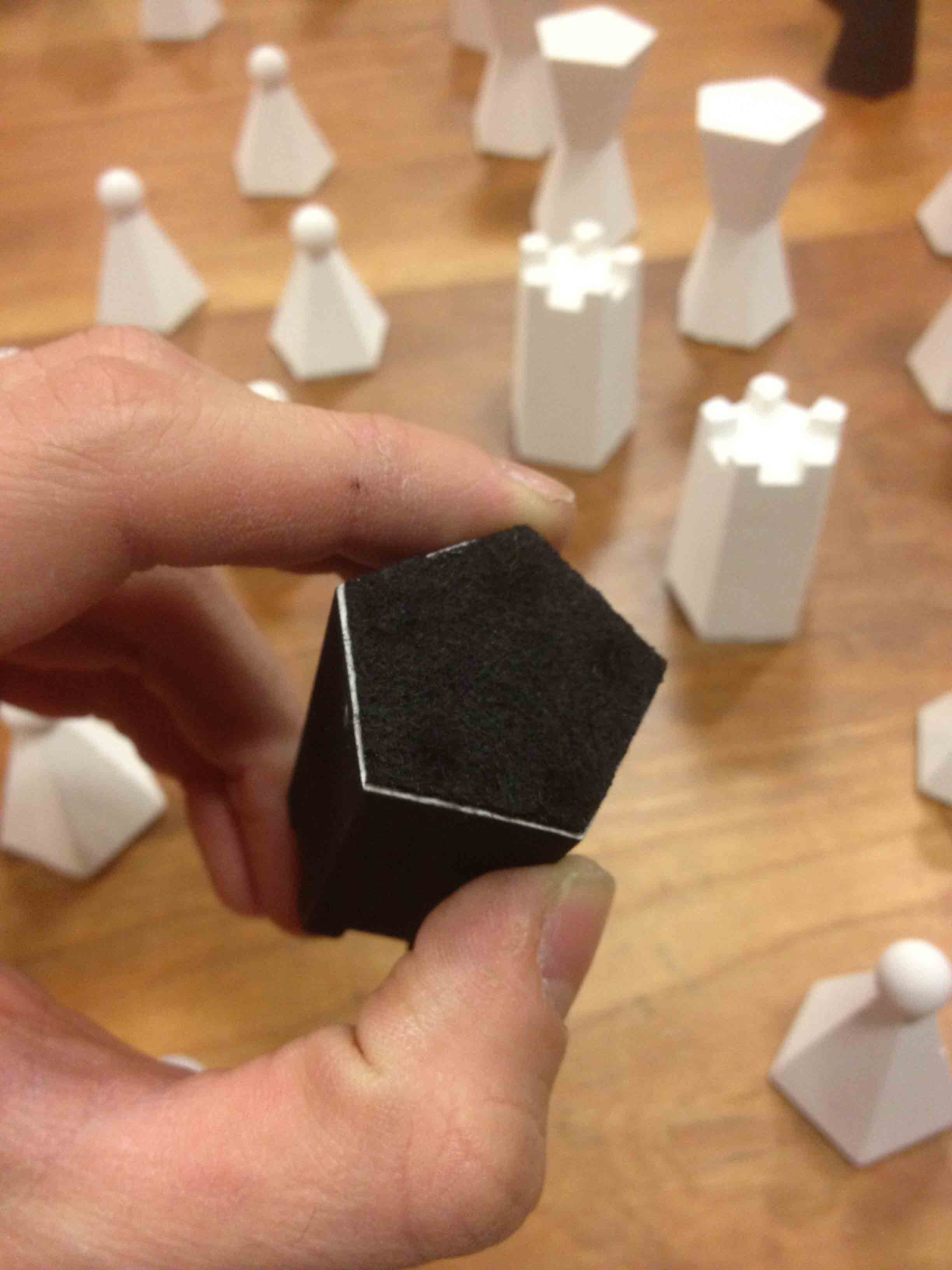
Once the pieces were done, I spray-painted half of them black.
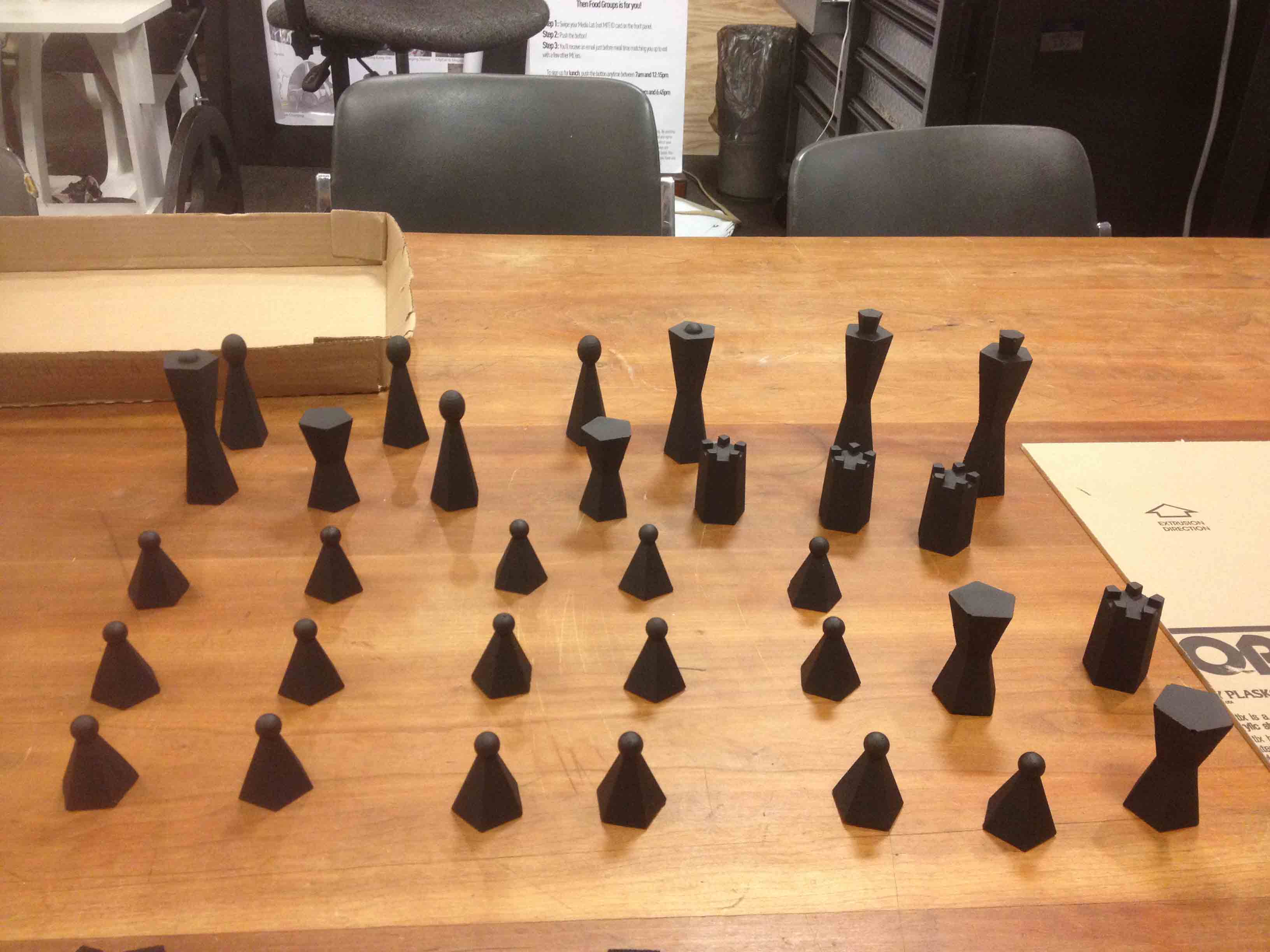
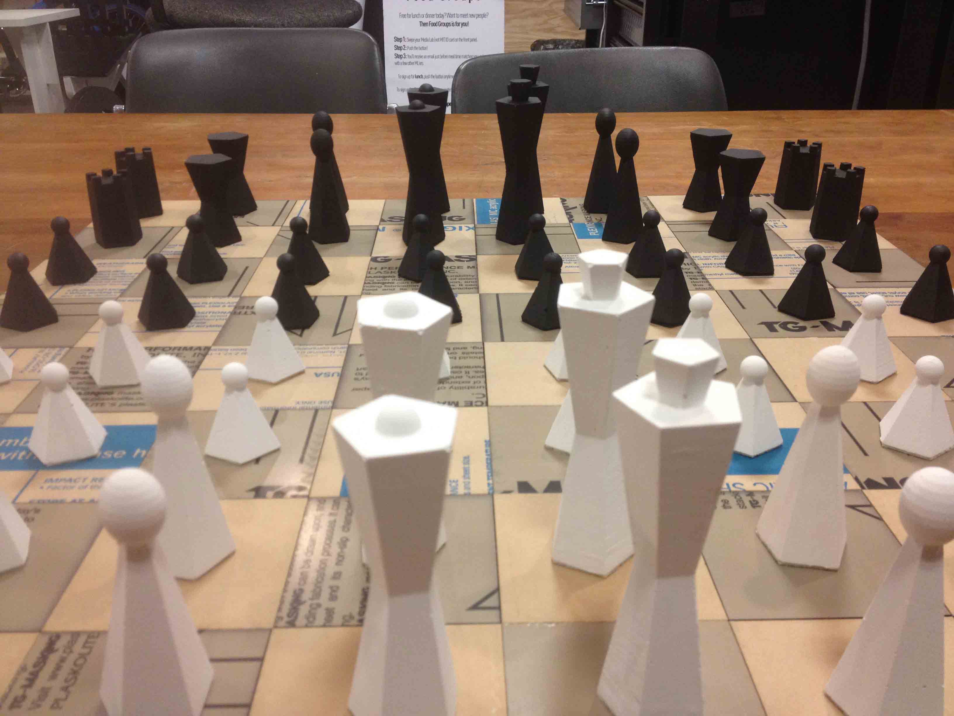
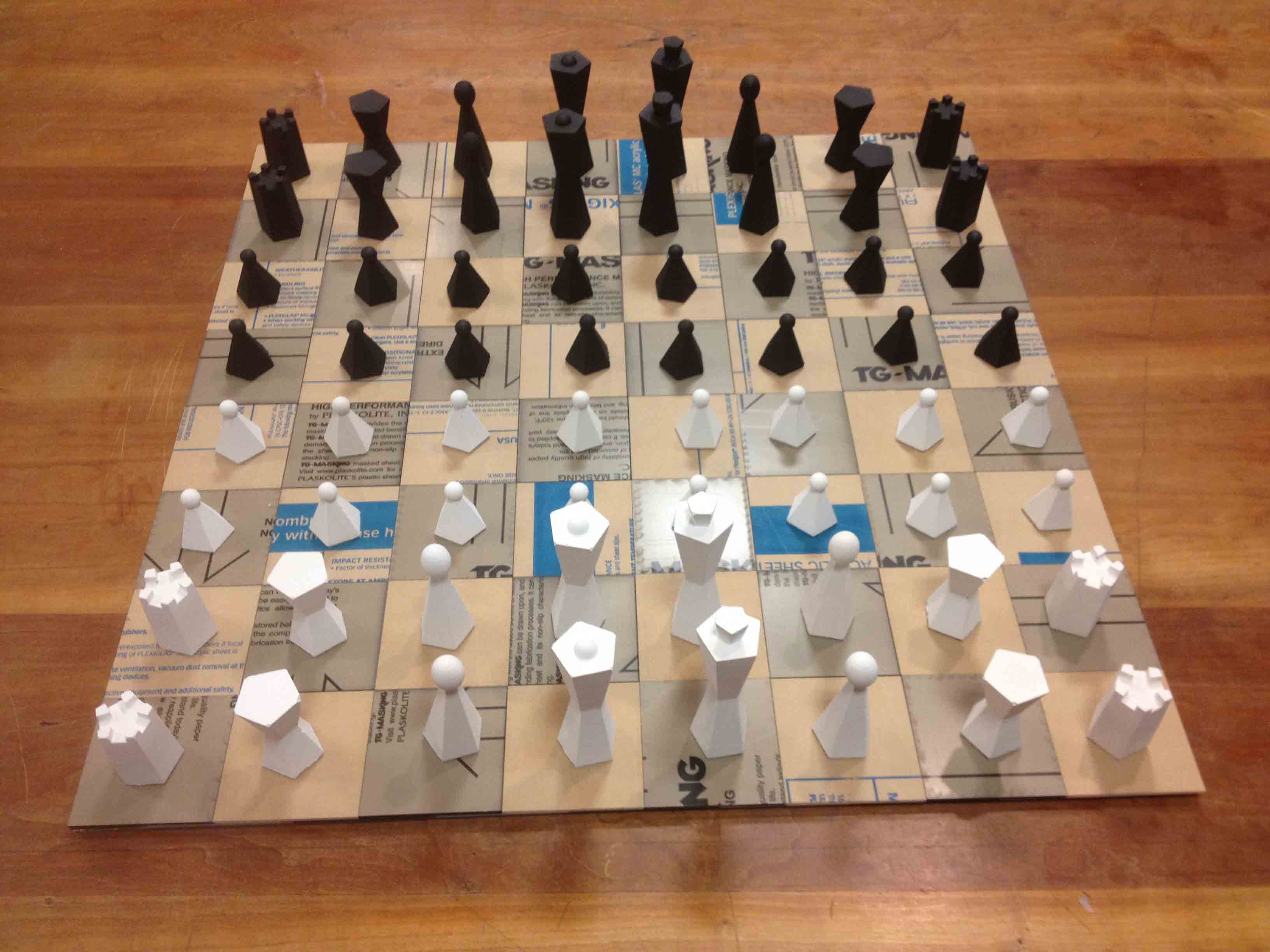
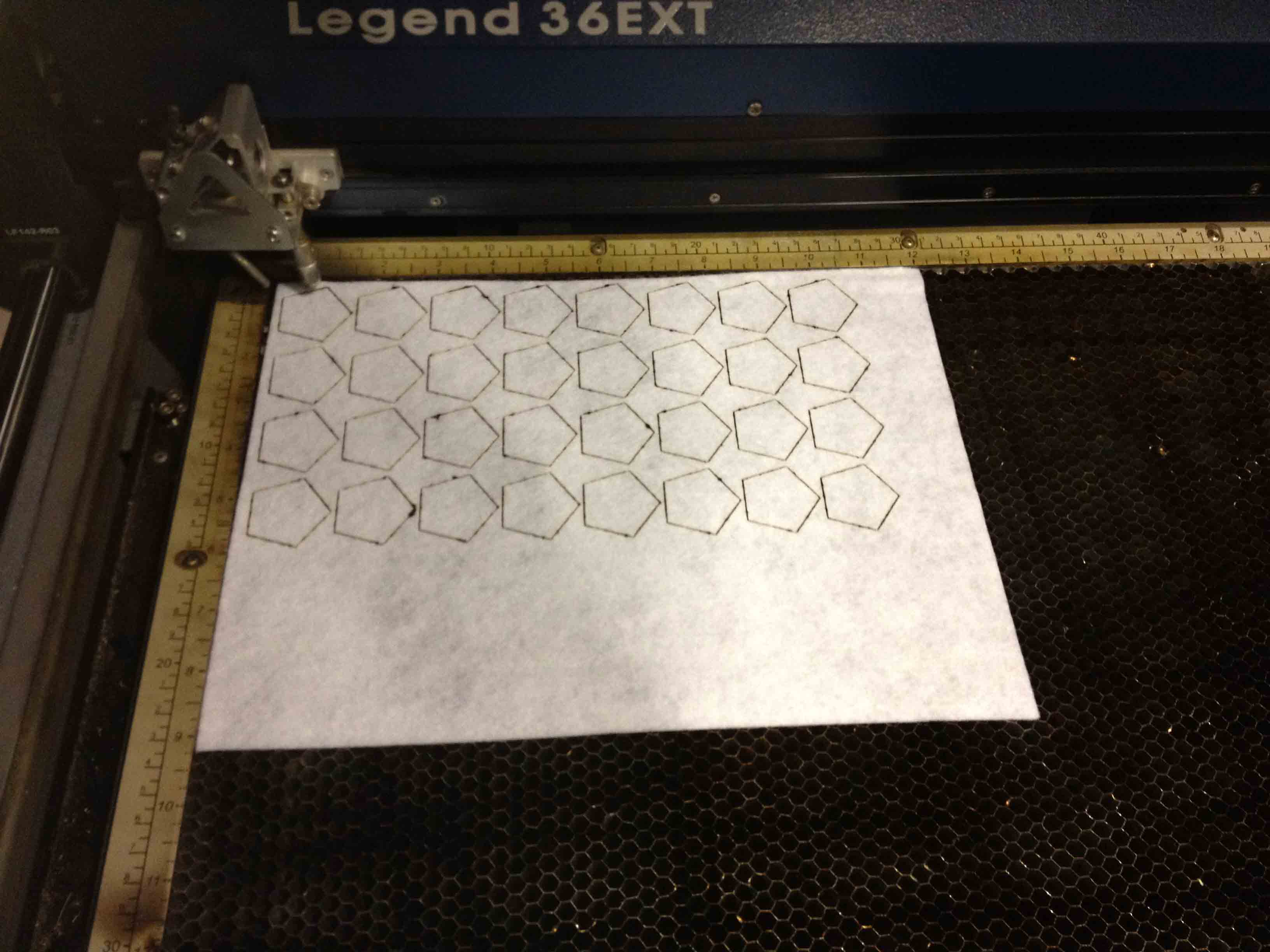
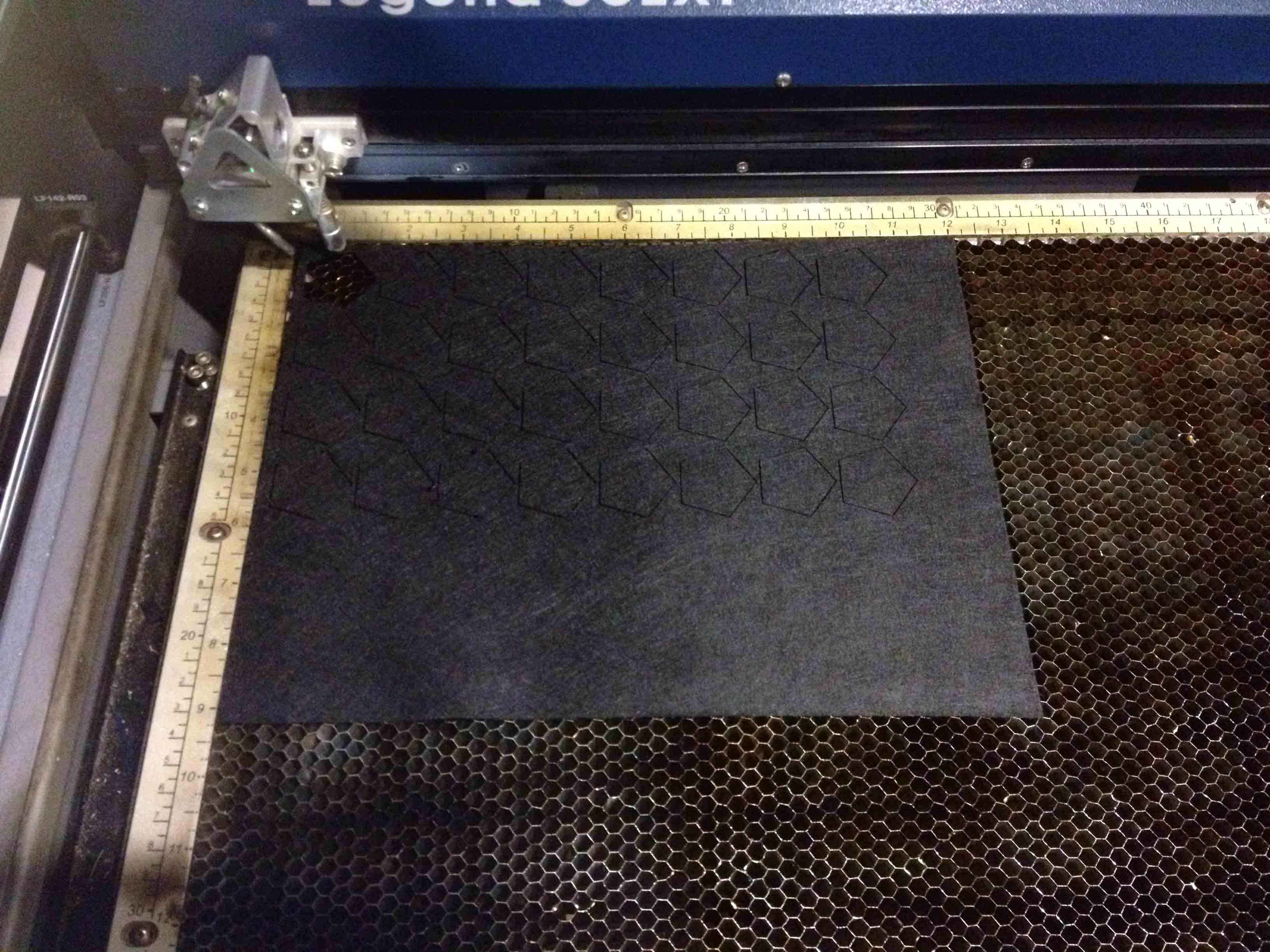
I also laser-cut black and white felt bottoms for all of the pieces and glued them on. Having the felt bottoms was not only a nice aesthetic touch, but also later protected the board from getting scratched, and allowed the pieces to move more smoothly across the squares.
Making the Board
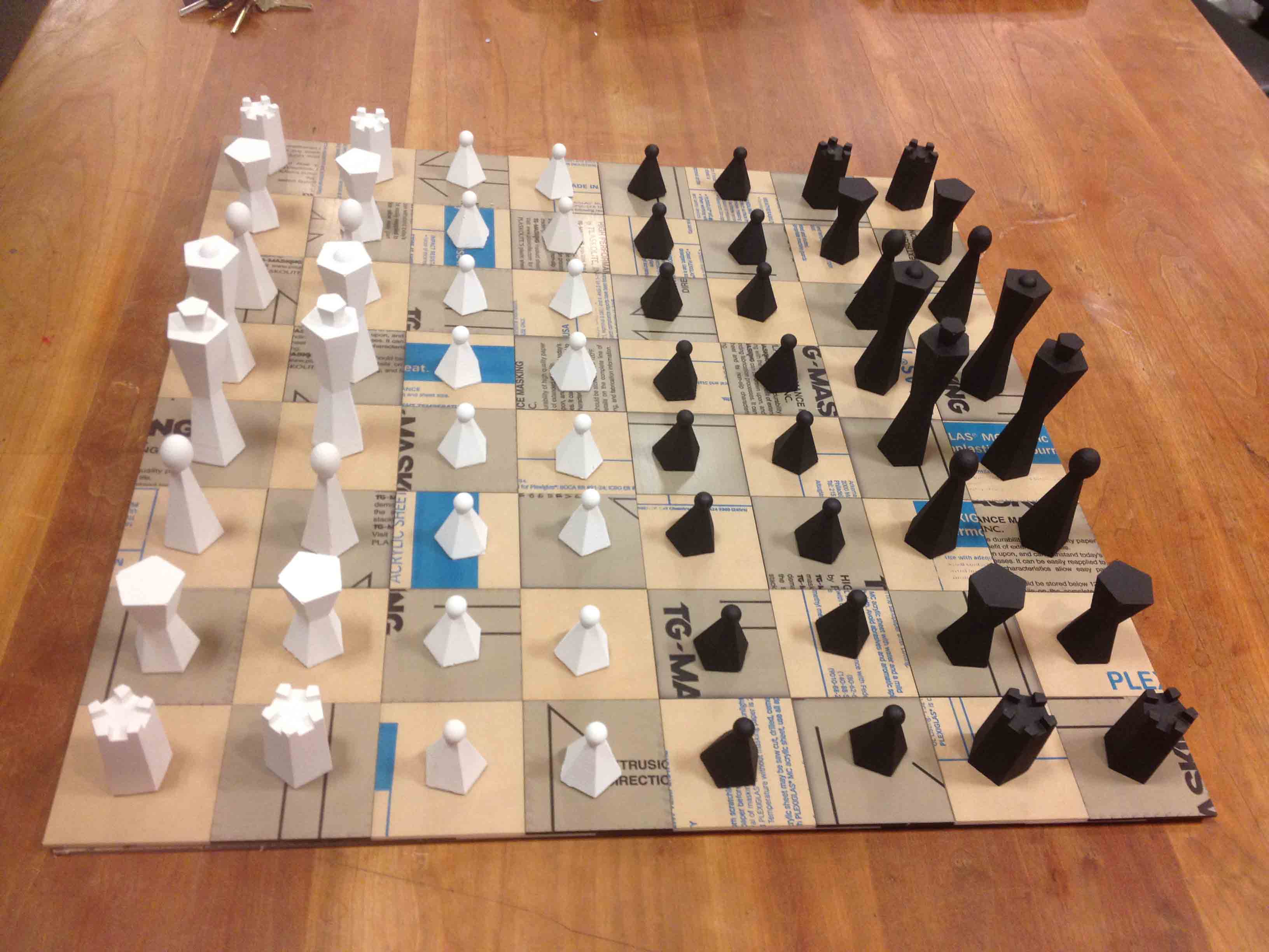
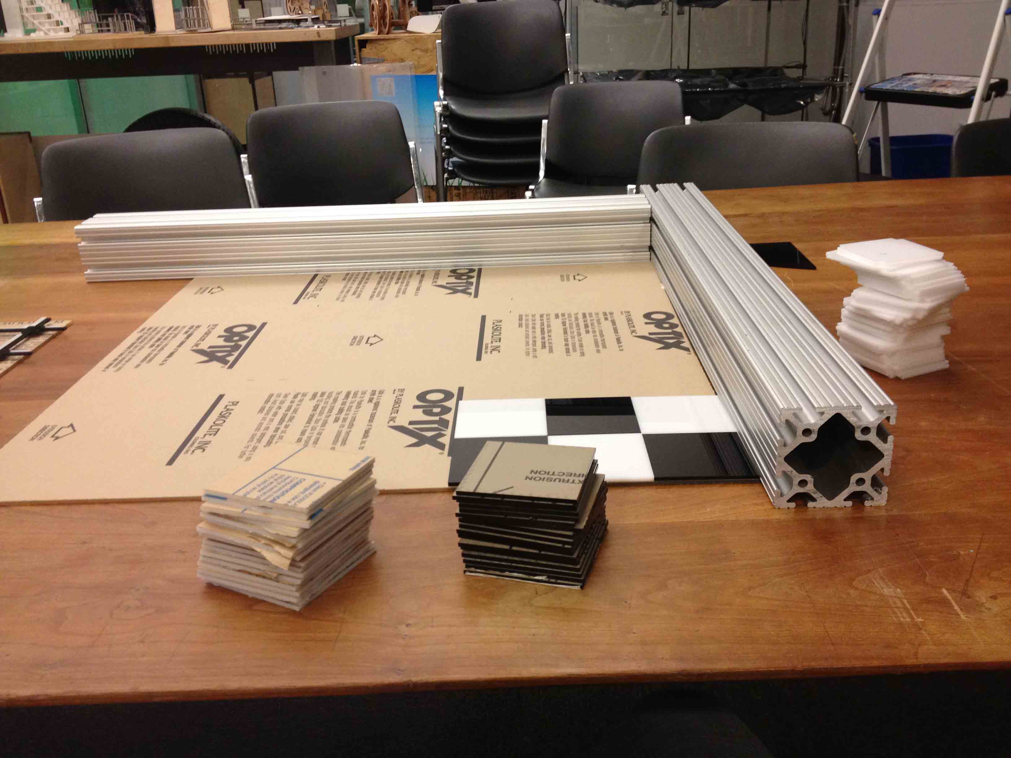
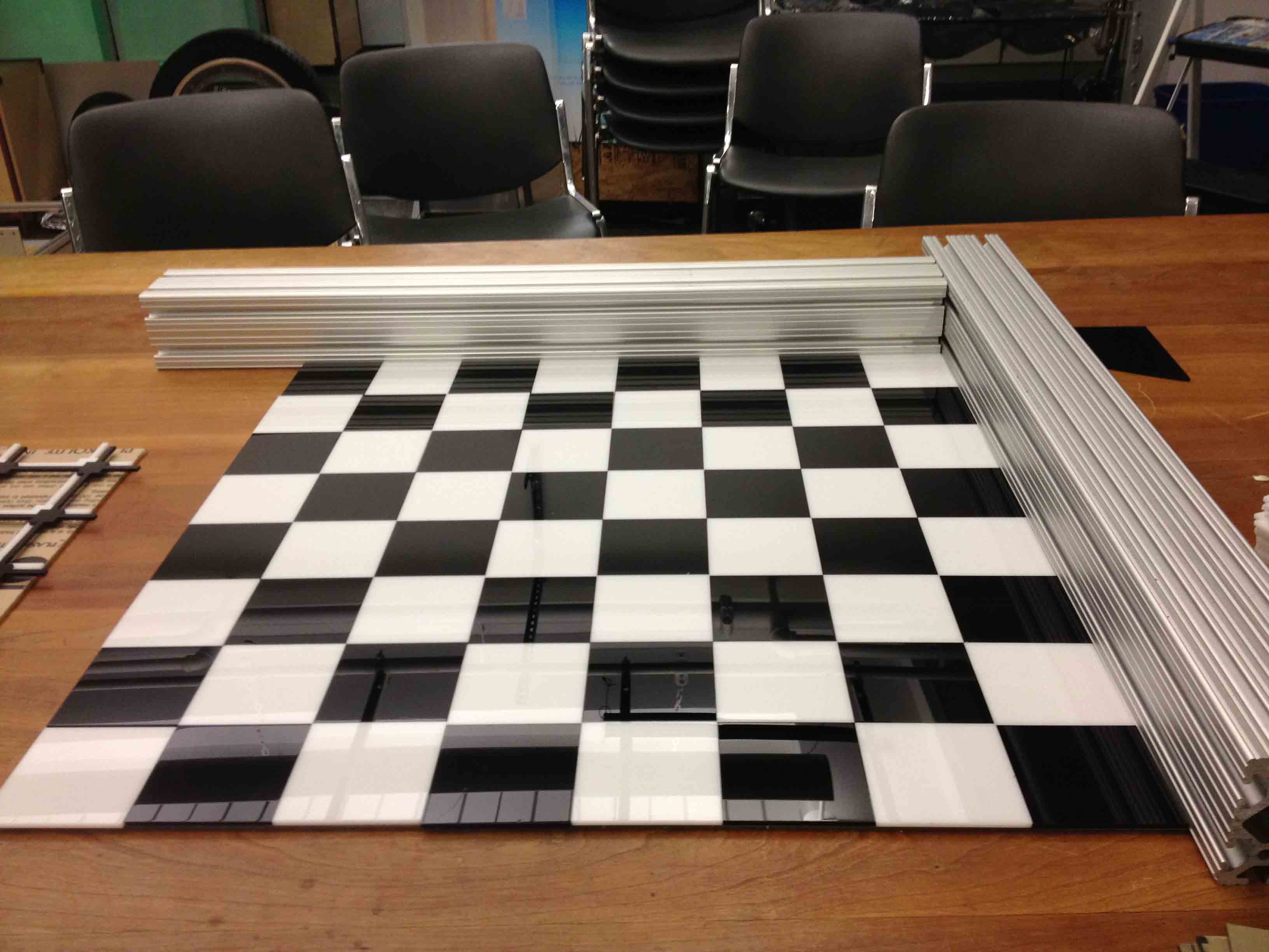
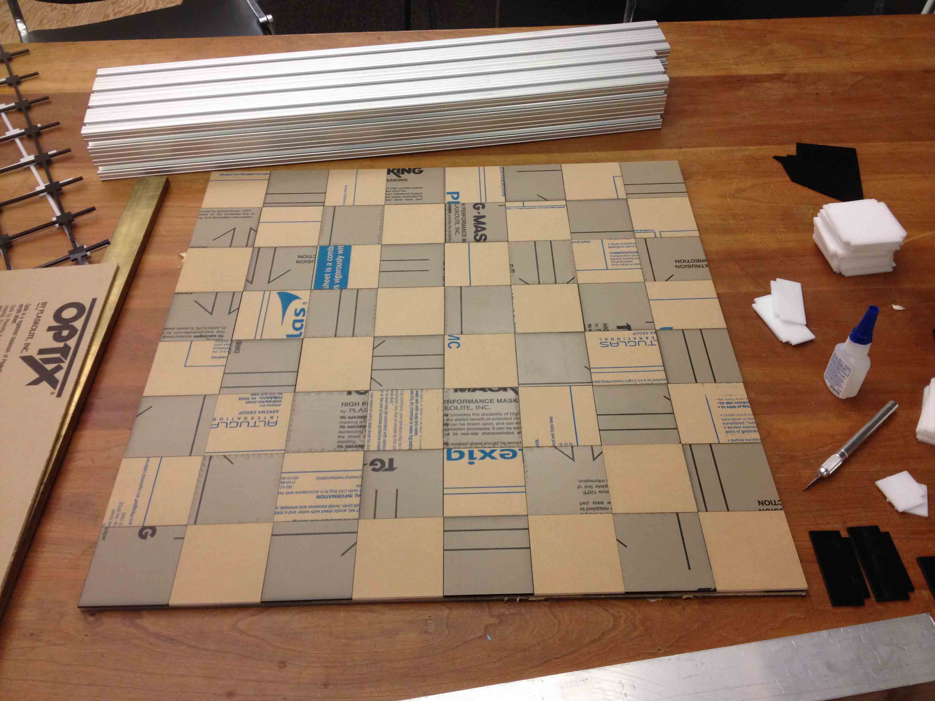
Making the board involved making the checkered structure itself as well as the sensing system to determine where the pieces are at any given time. I first laser-cut 64 black squares and 64 white squares (32 of each for each board) out of 1/8" thick acrylic, as well as a similar number of slotted squares to hold the structure together and provide pathways for the sensors and wiring underneath each square.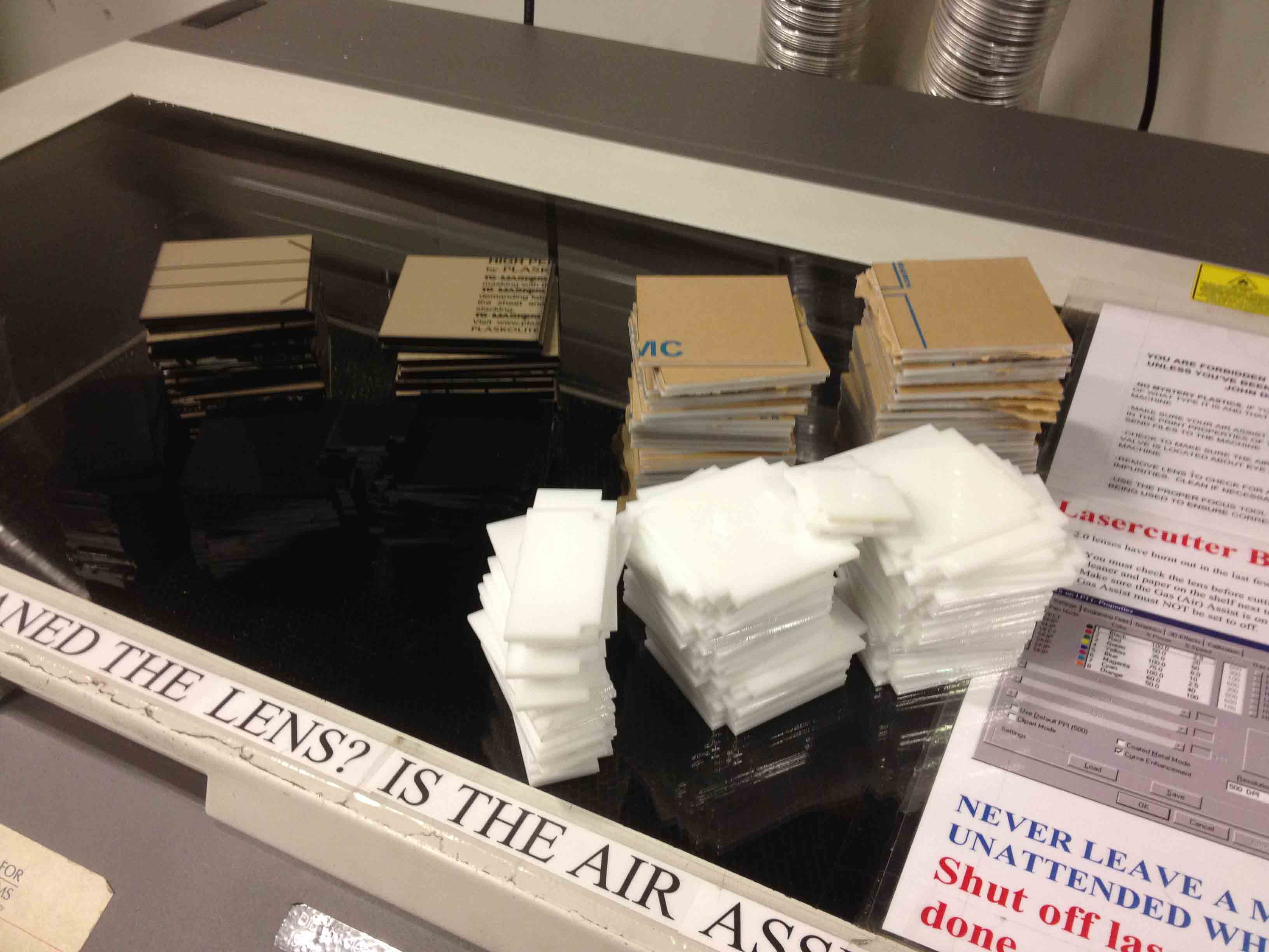
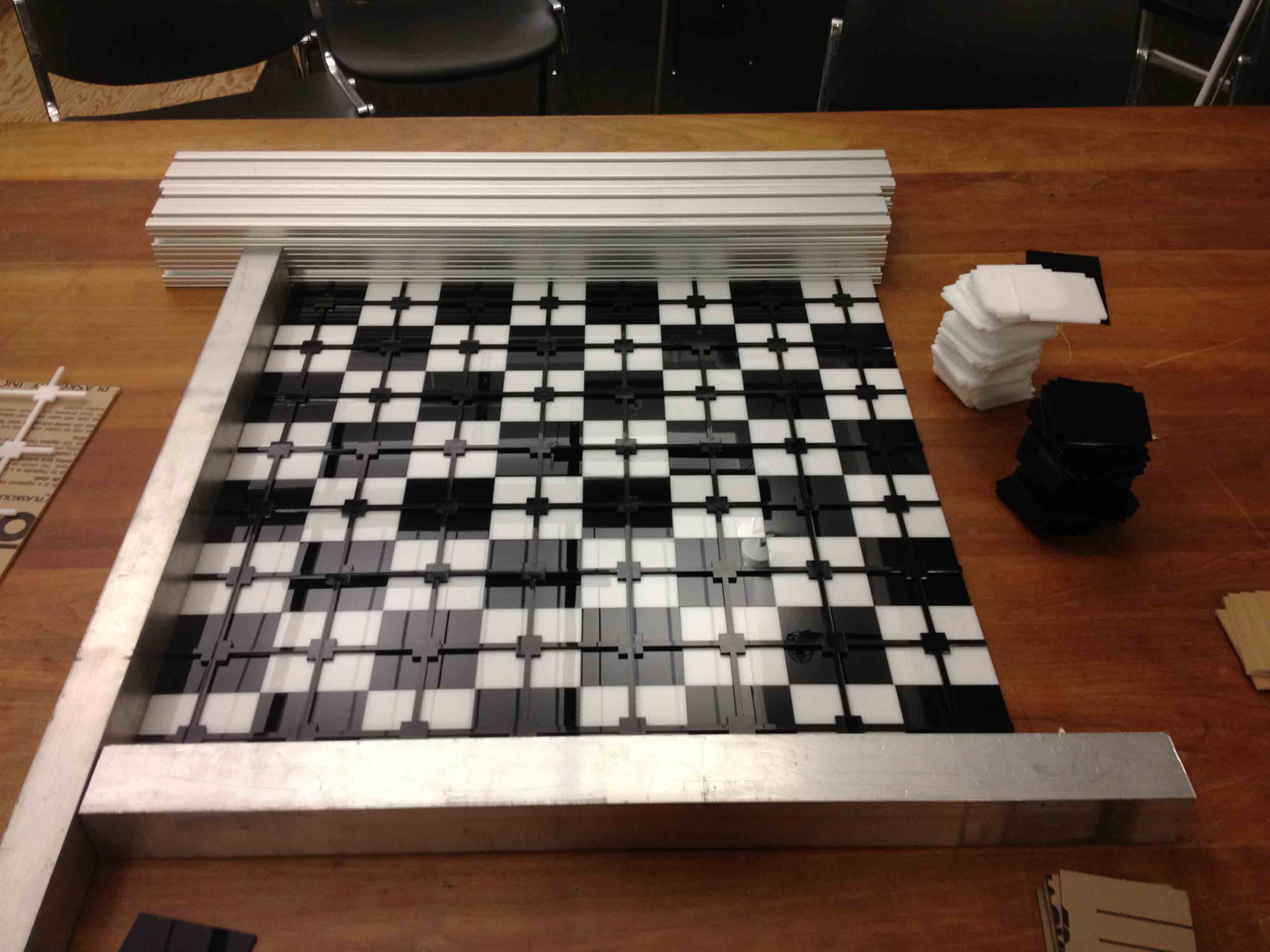
I laid them out in alternating colors, using some straight metal beams I found to keep them perfectly square.
I used the negative scrap acrylic piece that was left over from cutting the slotted squares as a template for aligning them underneath the board when gluing them on.
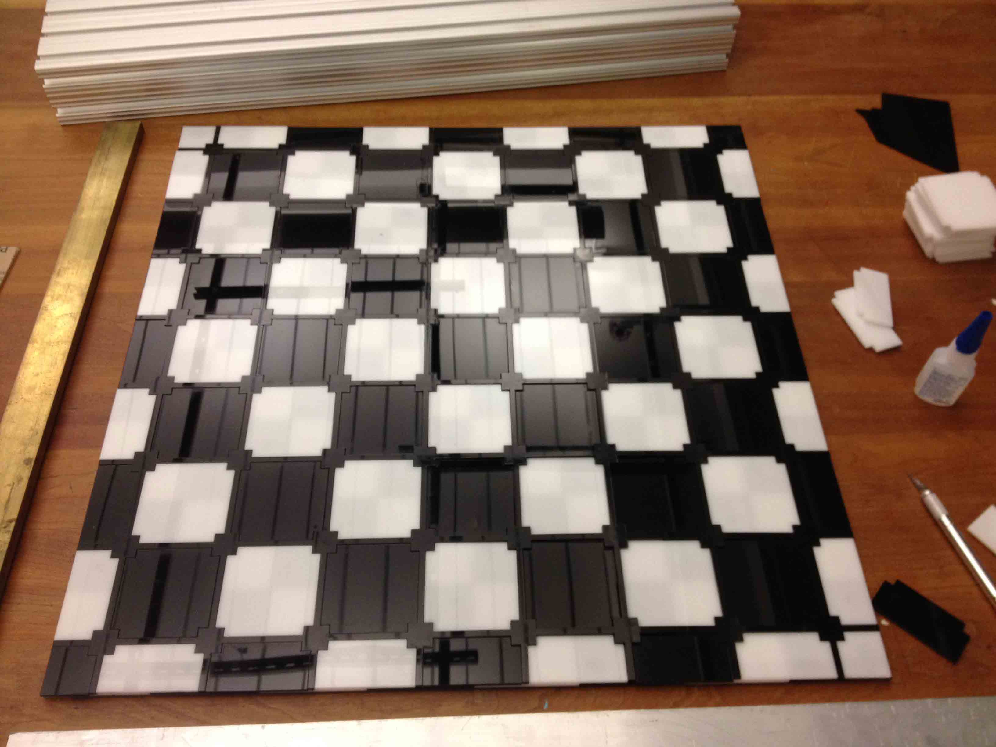
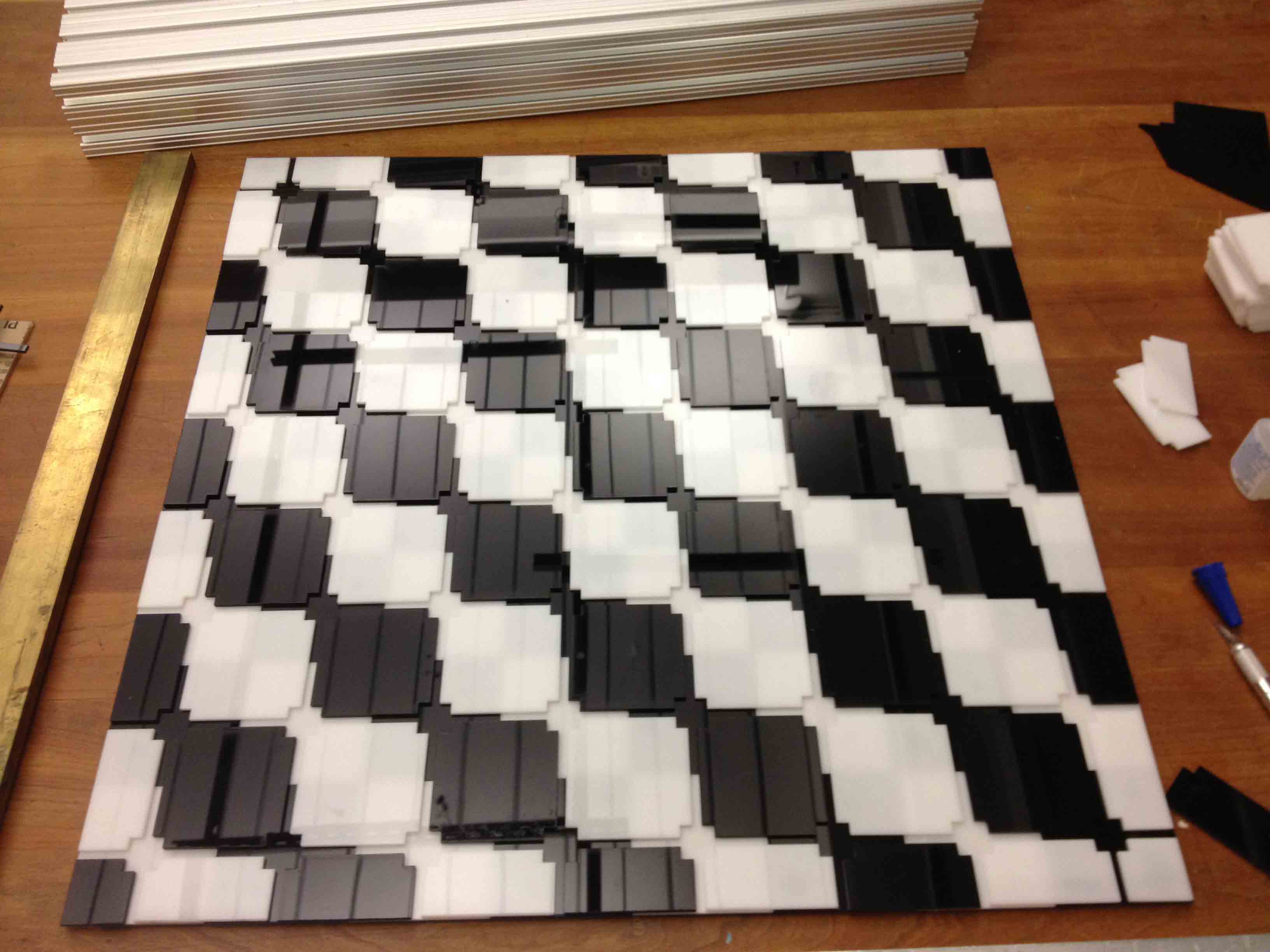
I left the protective paper covering on the front of the board until the very end to protect it from scratches.
Making the Sensing System
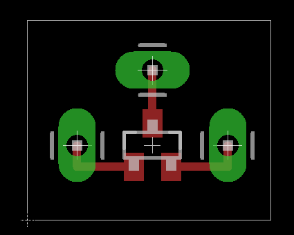
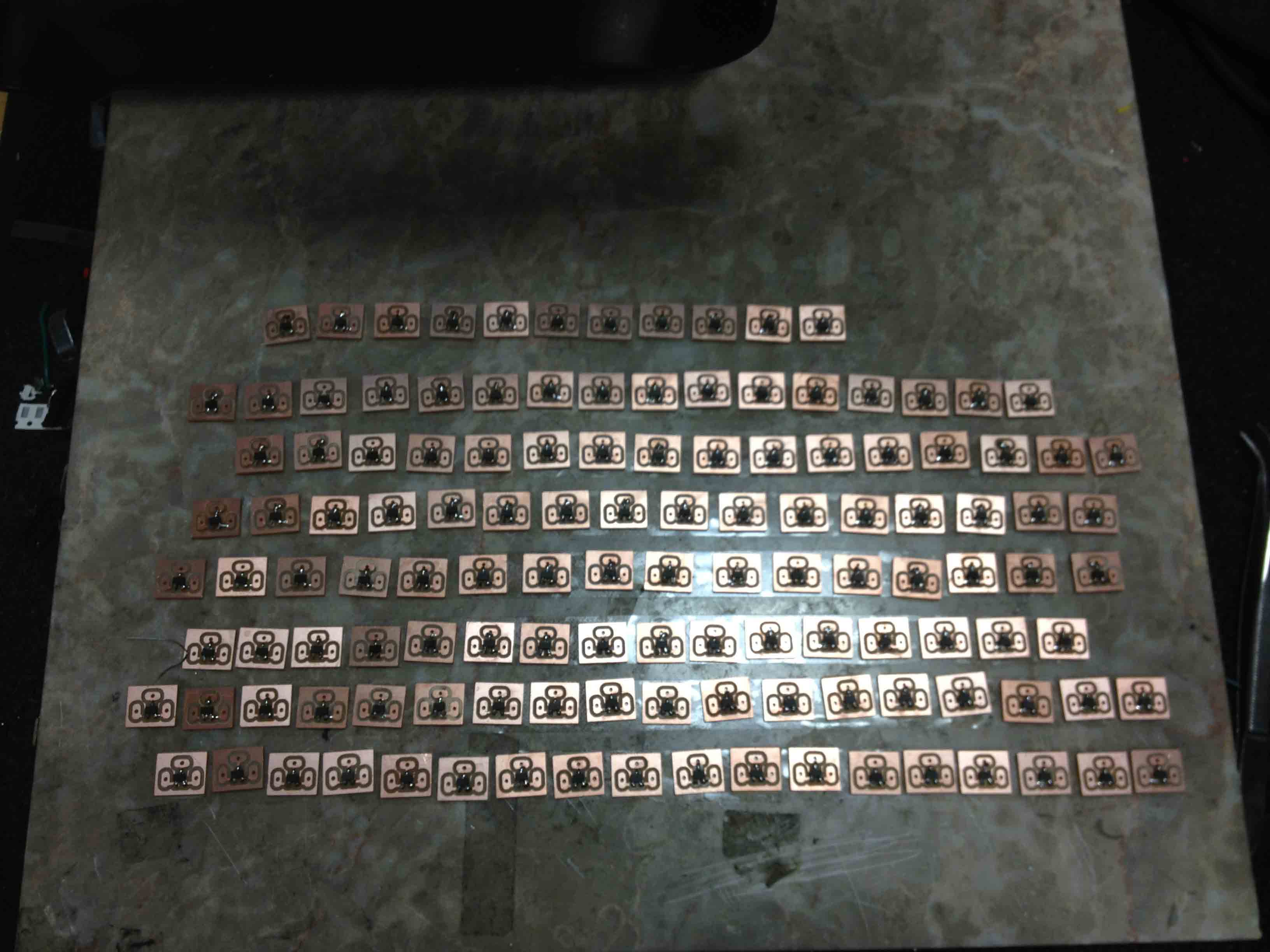
I designed a little breakout board for a surface mount hall effect sensor (magnetic sensor) in Eagle and used the Modela to mill out 128 of them (one for each square on each of the two boards).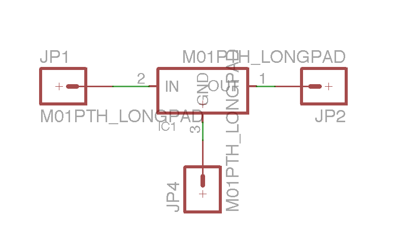
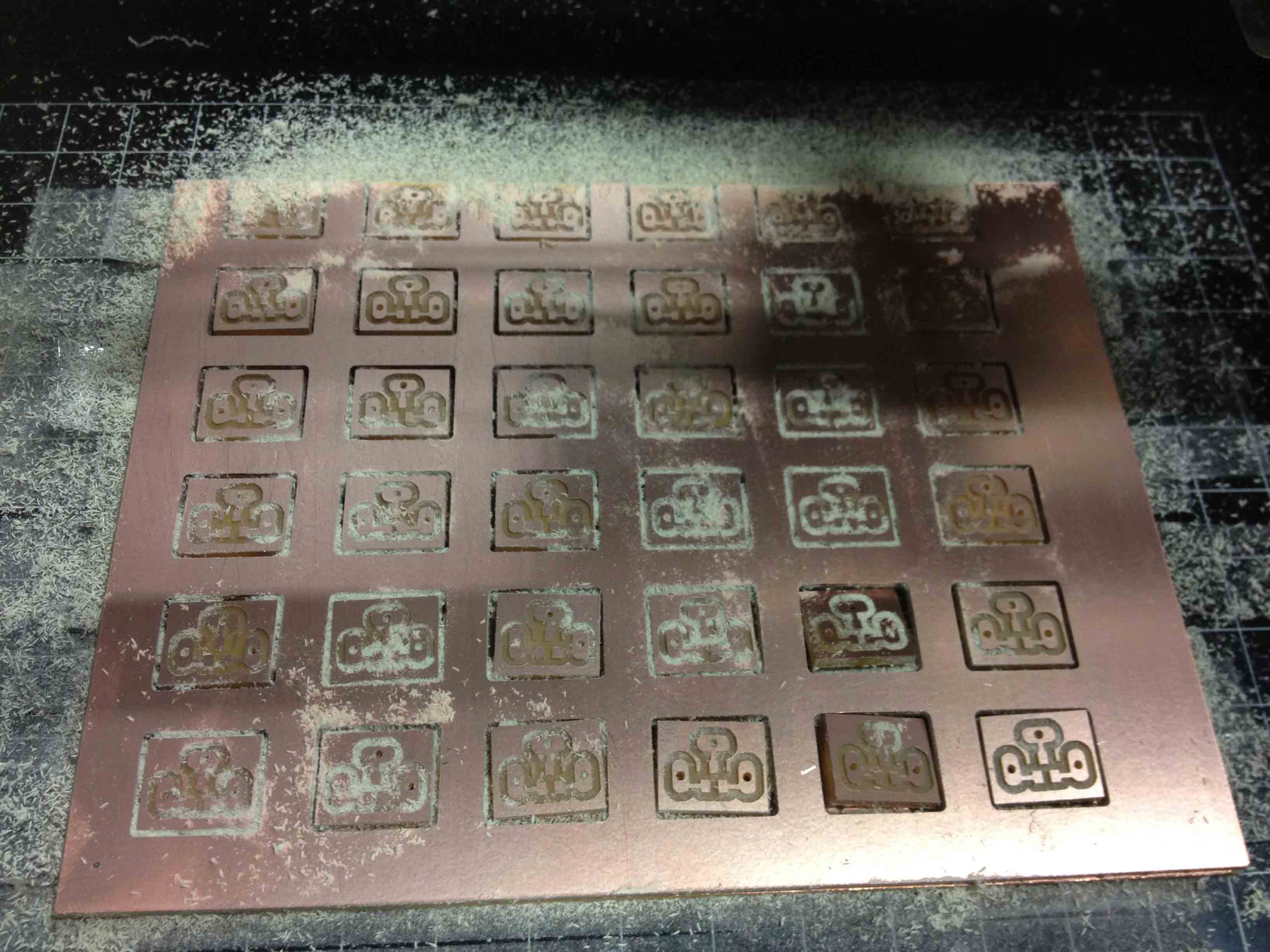
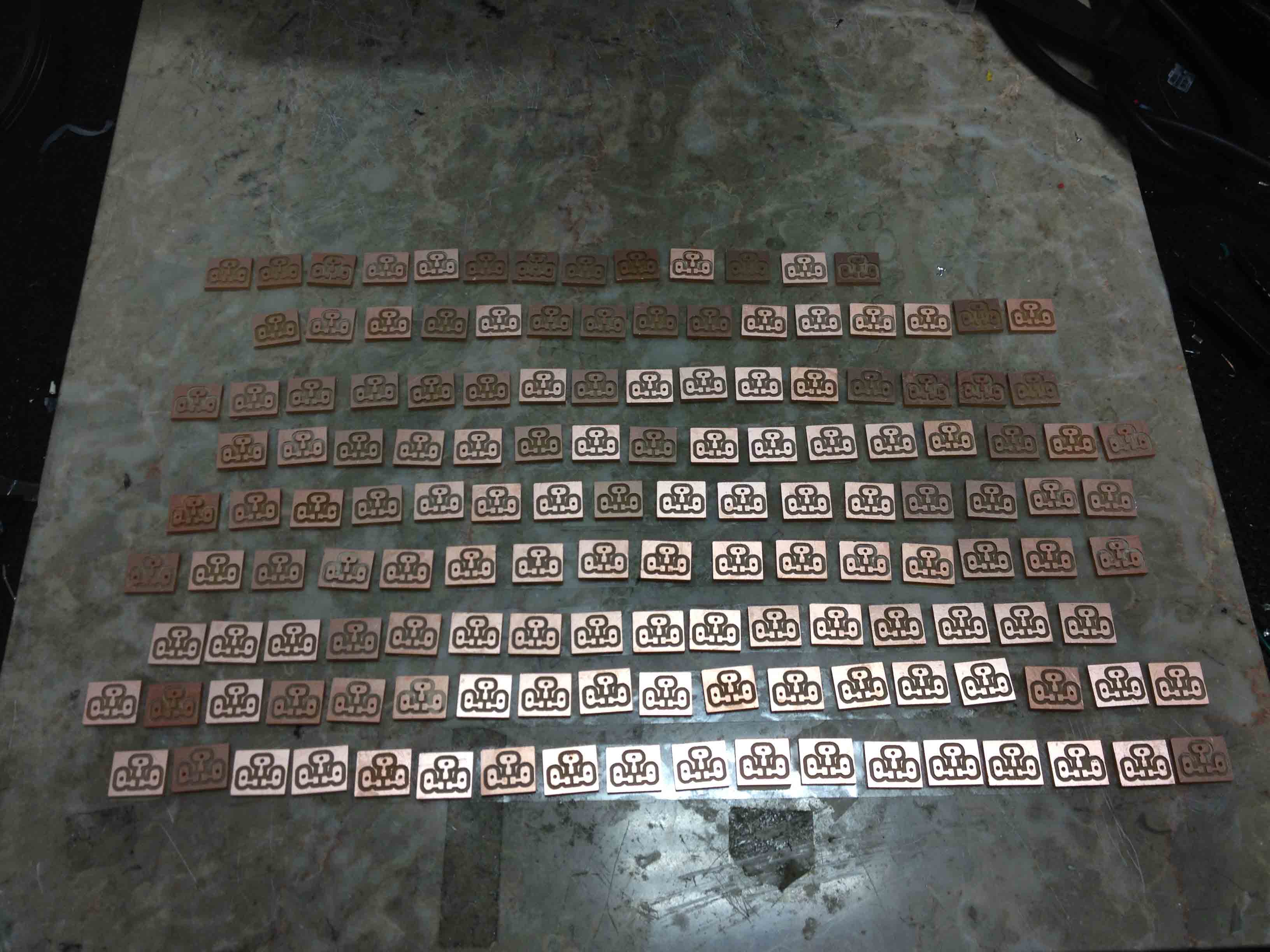
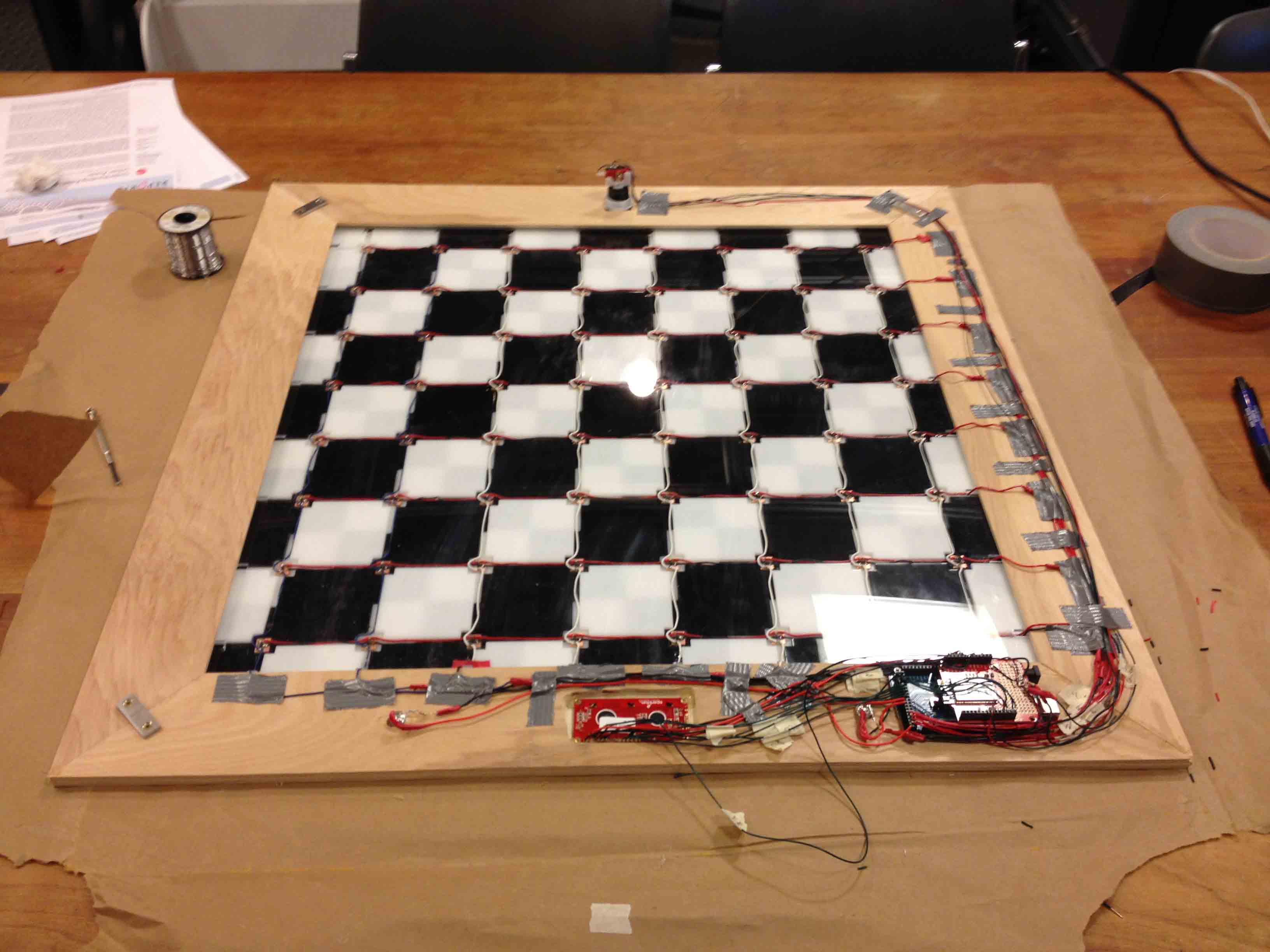
I then (painstakingly...) soldered 128 hall effect sensors to them, and positioned them between the slotted squares on the back of the acrylic board using double-sided tape (which is surprisingly strong). The slotted squares are arranged in such a way that the circuit boards are positioned in the middle of each actual square.
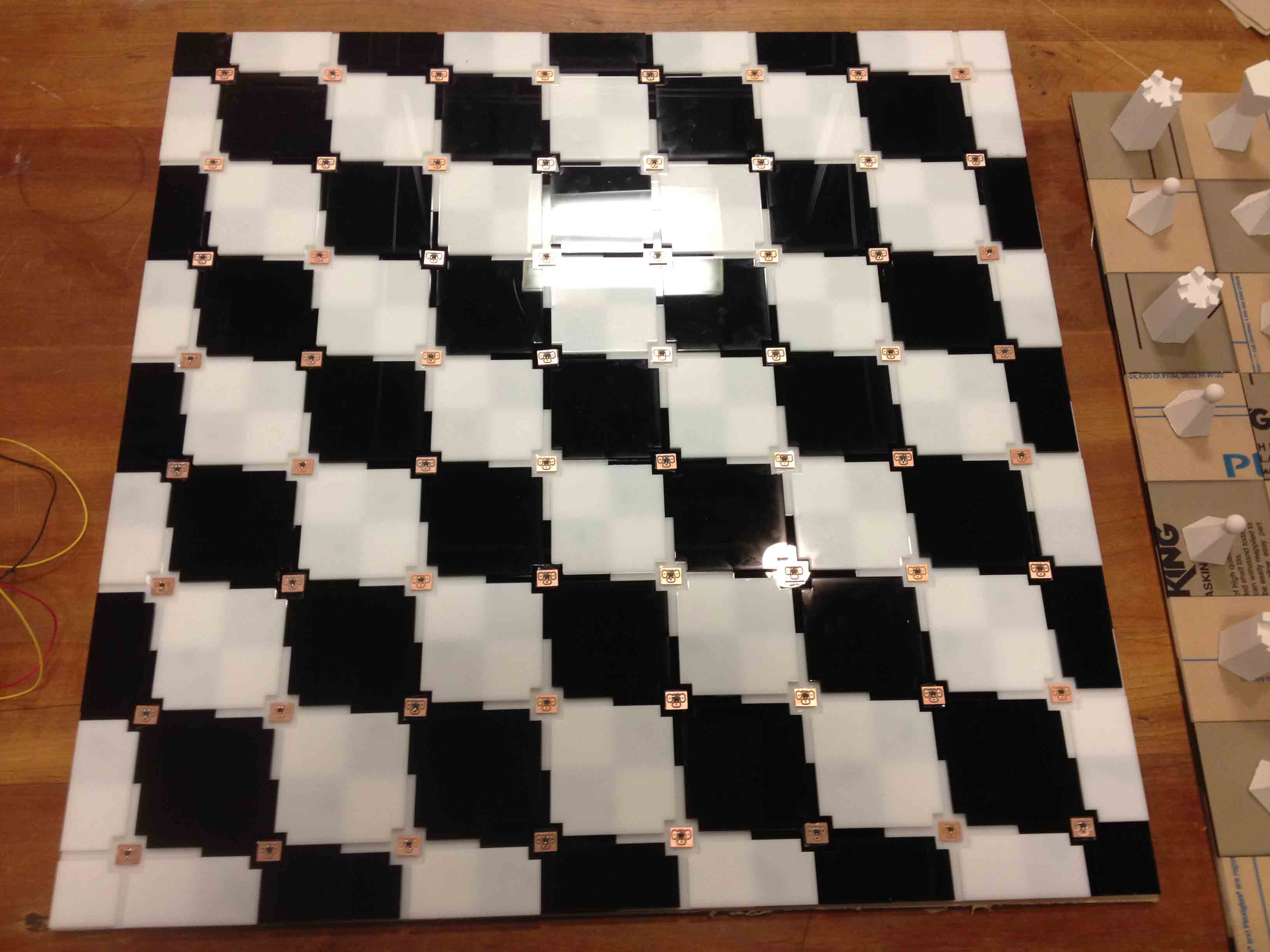
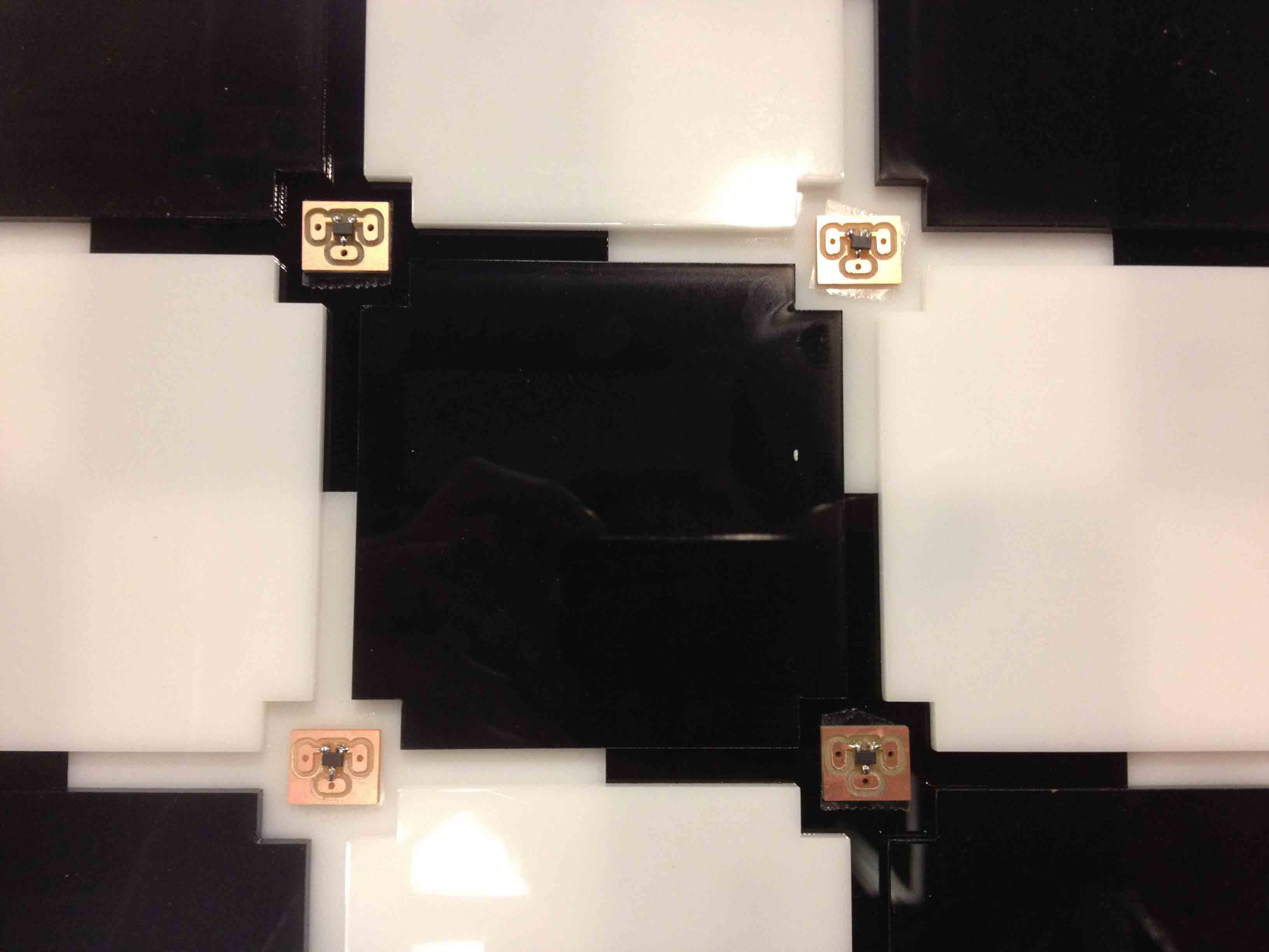
I then connected them all with hook up wire in a grid-like pattern, with one wire emerging out of each row and column. By supplying power to a particular row and reading out the voltage level of a particular column, I can target any of the 64 sensors with only 16 I/O pins on my microcontroller.
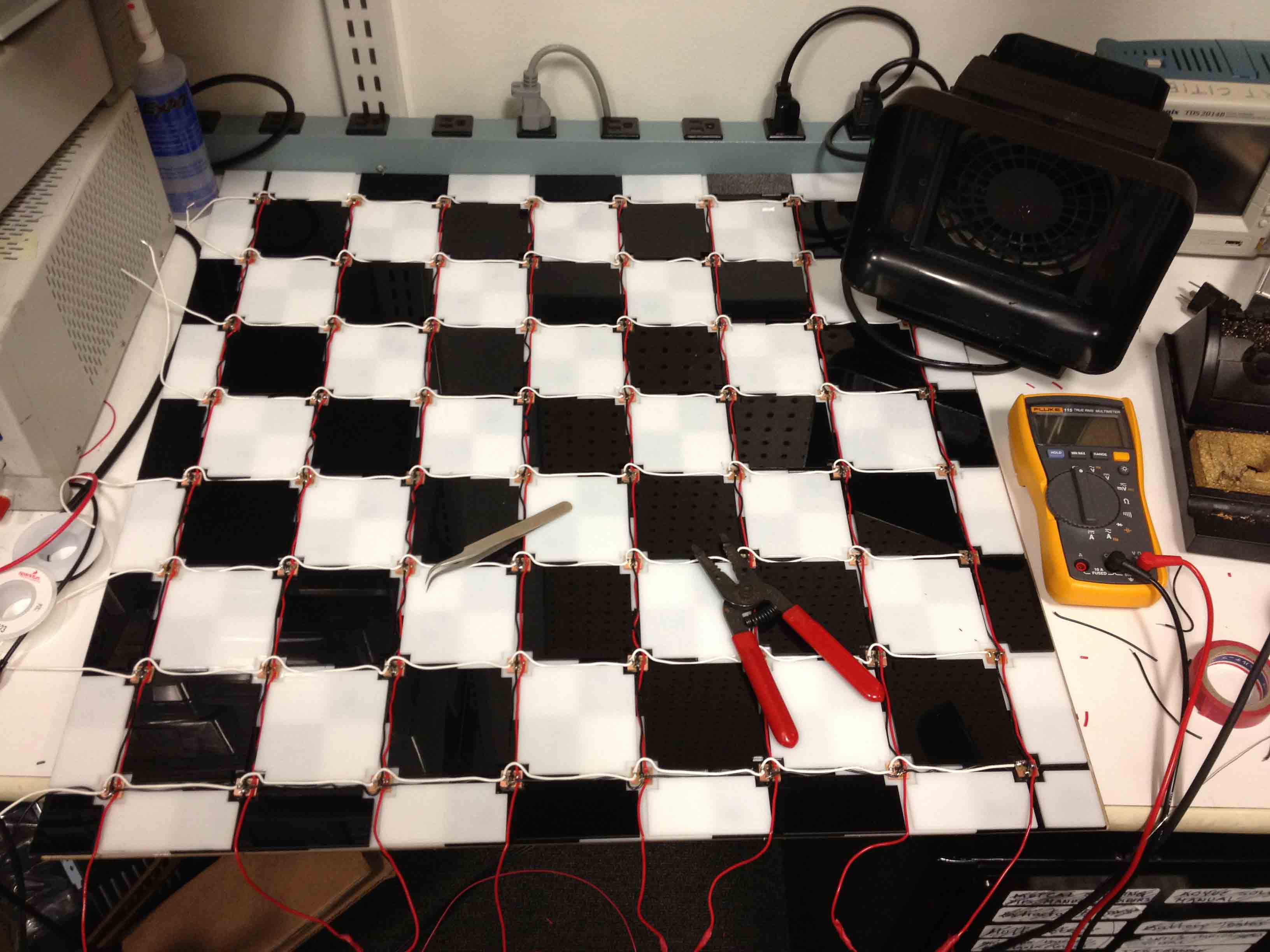
I also lasercut a clear piece of acrylic with slits at the edges to both support the board as well as provide a space for the wires in each row and column to stick through.
At this point, I hooked up the wires to an Arduino to test that it was working properly.
Making the Enclosure
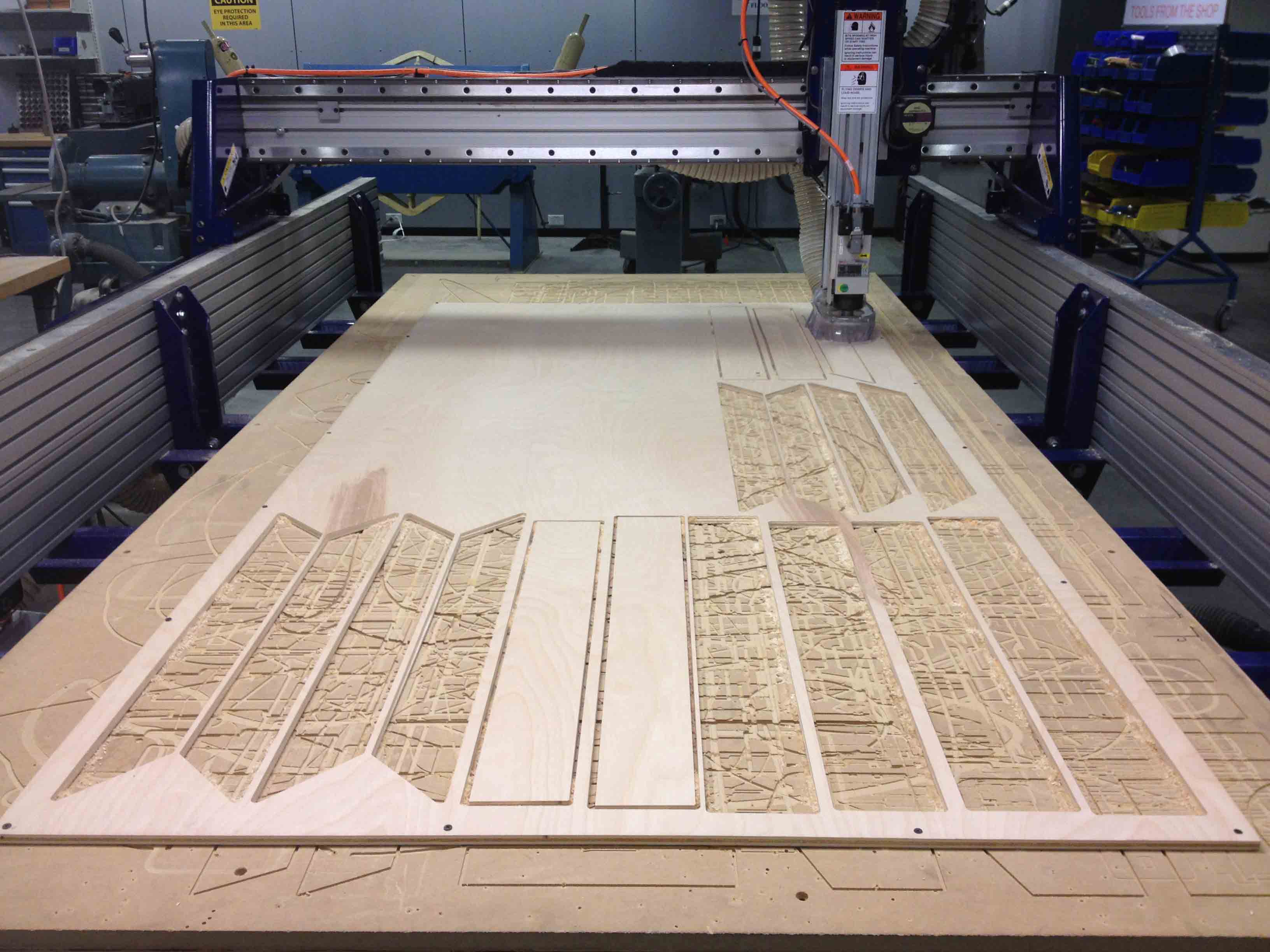
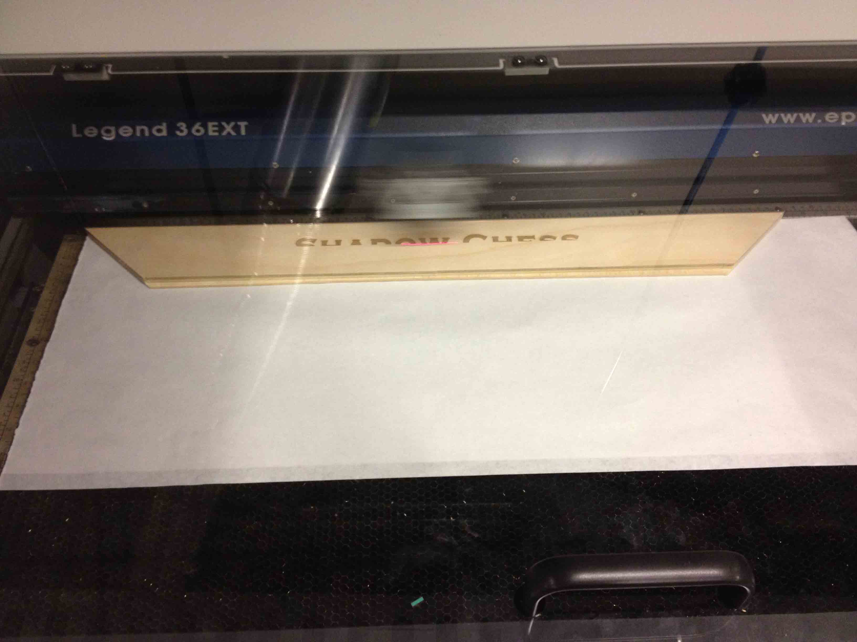
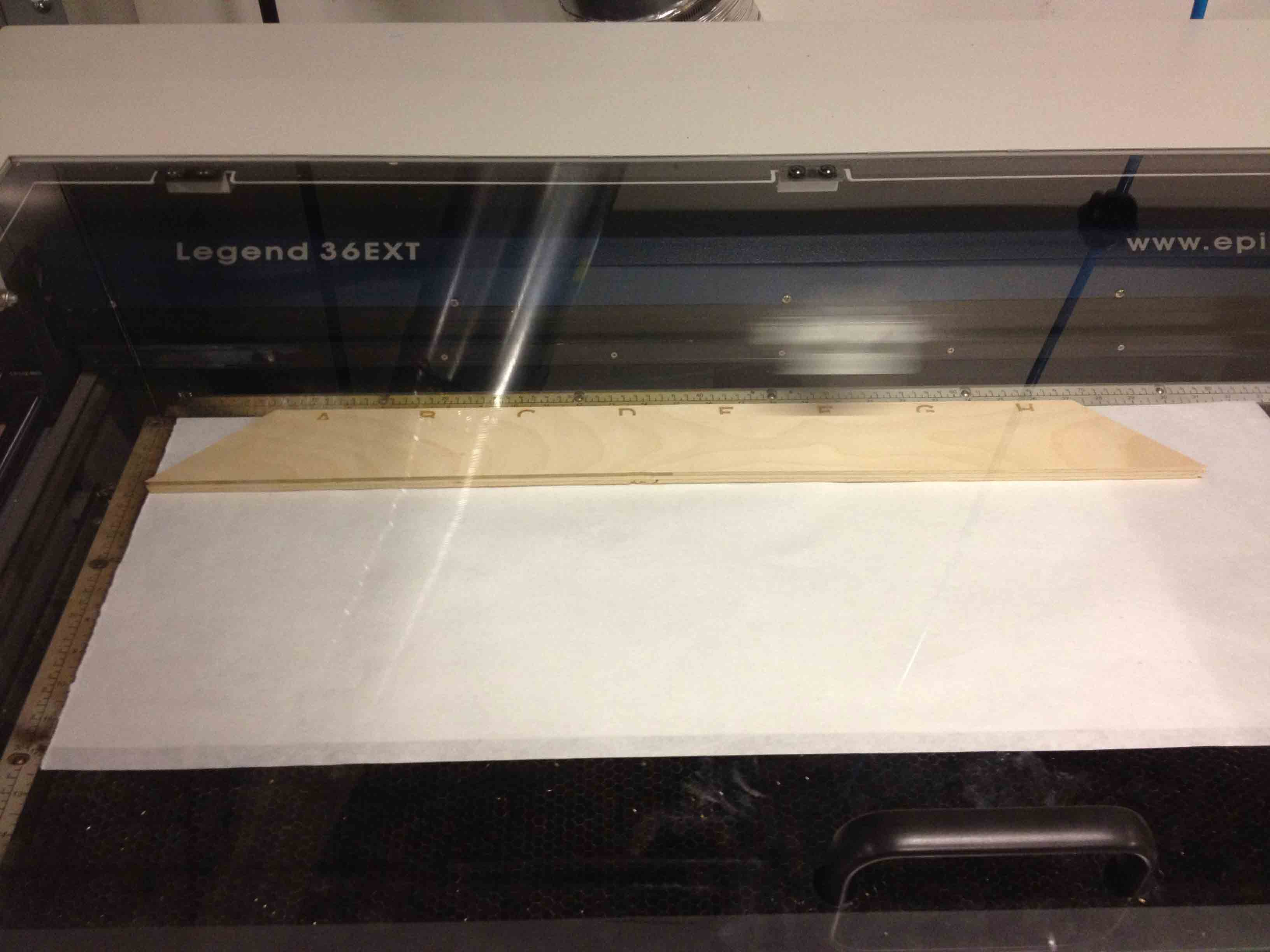
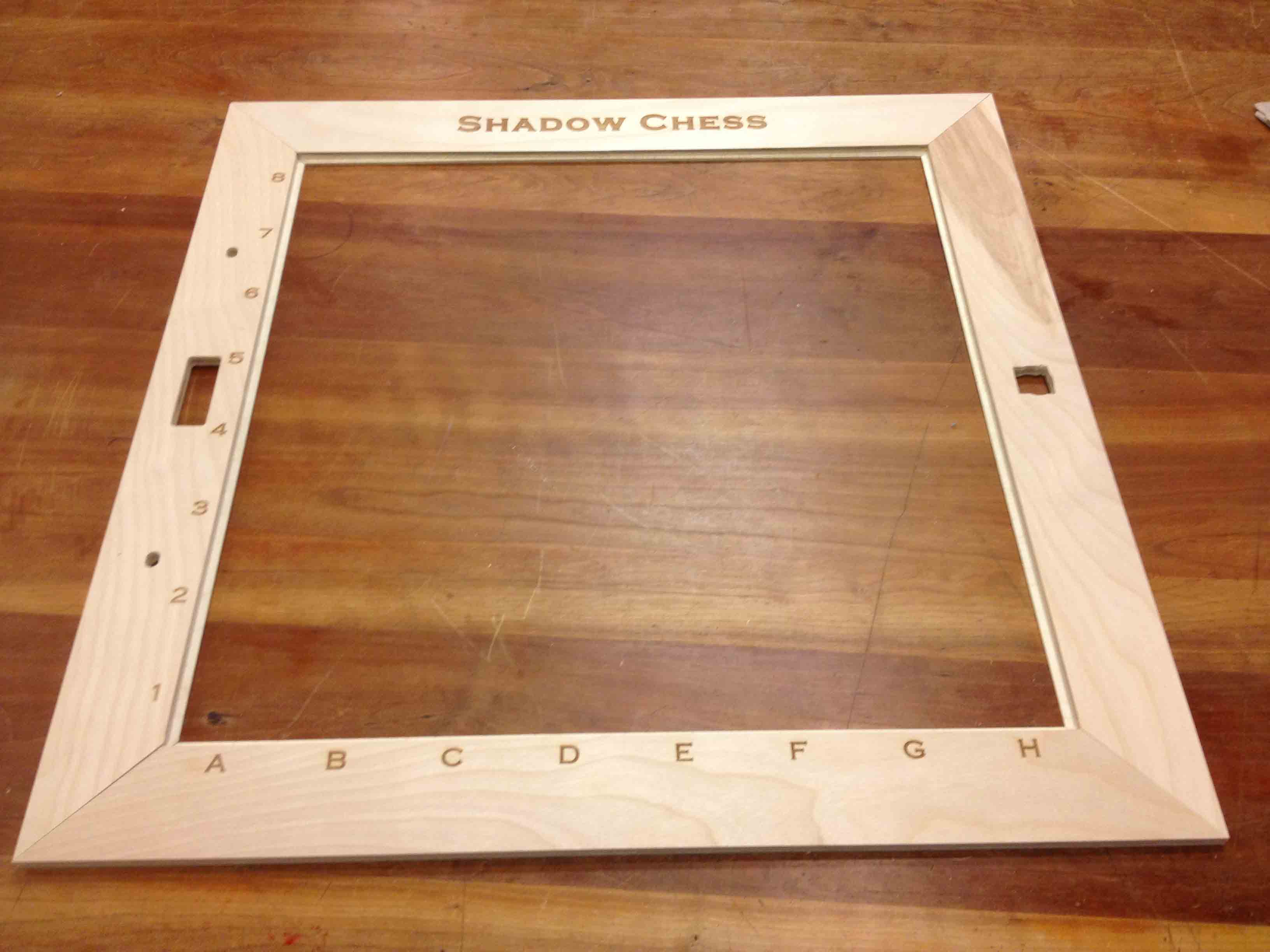
I designed the chess board enclosure so that it could house the mechanical equipment needed to move around the pieces as well as to fit the electronics needed to drive the board. I designed it in AutoCAD, and used the ShopBot to cut it out of a 4'x8'x1/2" sheet of baltic birch plywood. For the slot that houses the LCD screen, I had to use a hand router to remove some extra material from the other side of the wood so that it would fit flush against the front surface of the wood.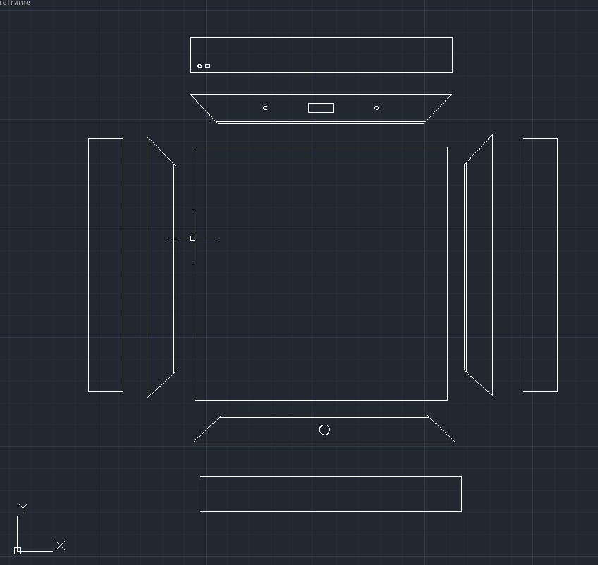
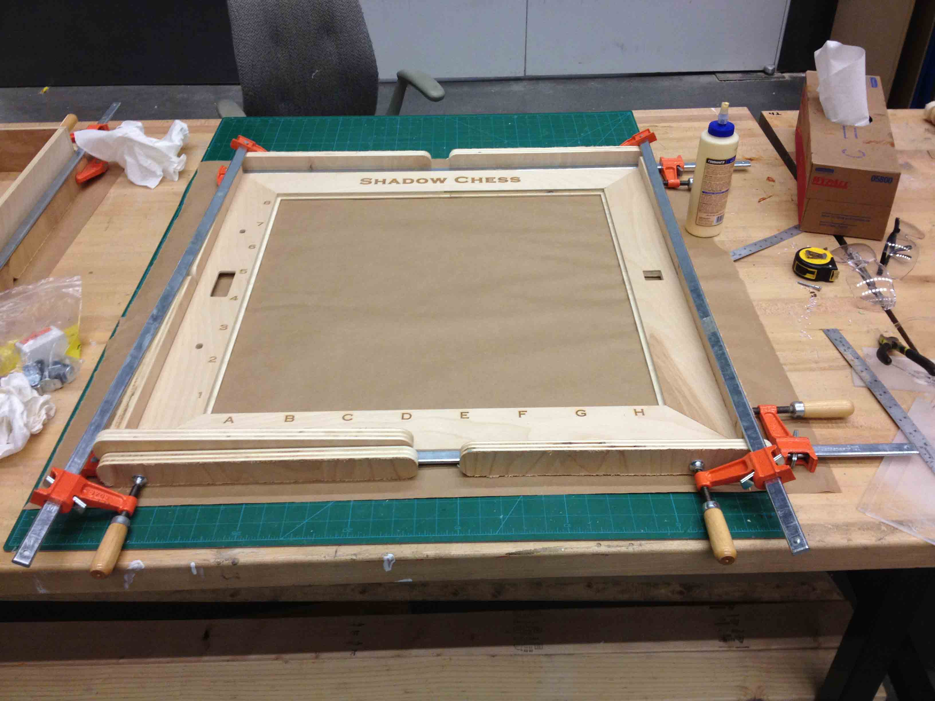
I also laser-engraved the name of the game and row/column markings on the wood.
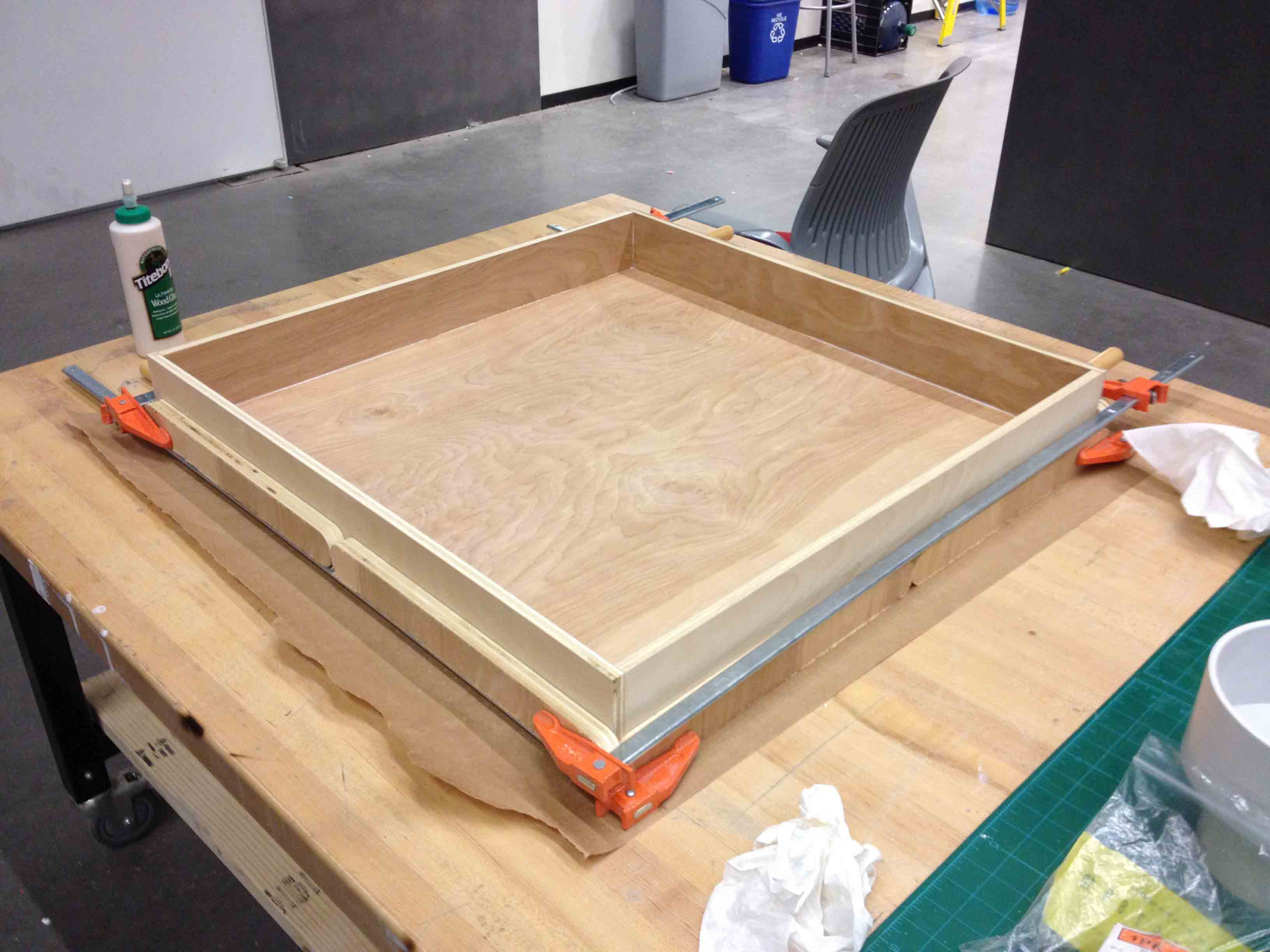
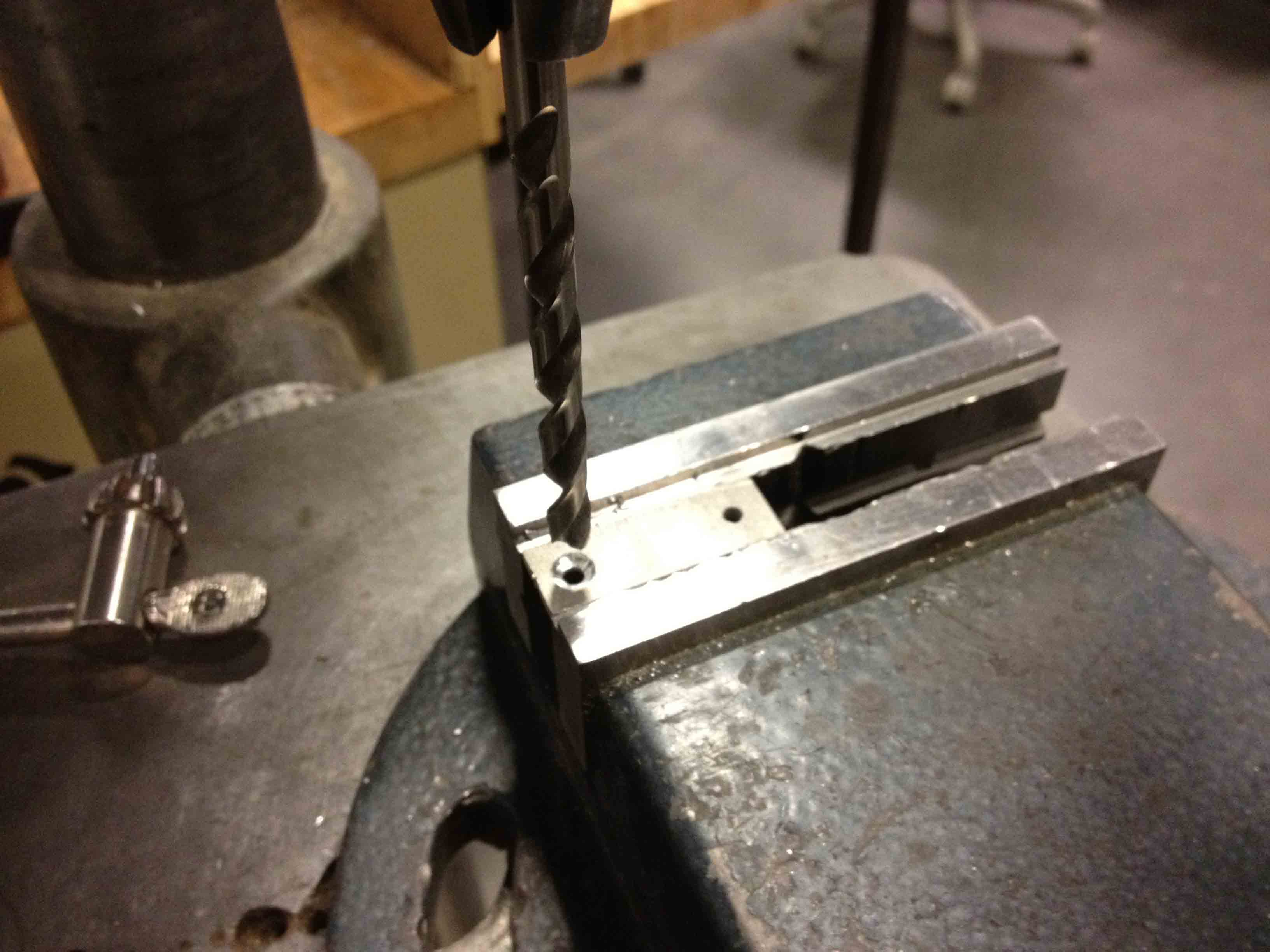
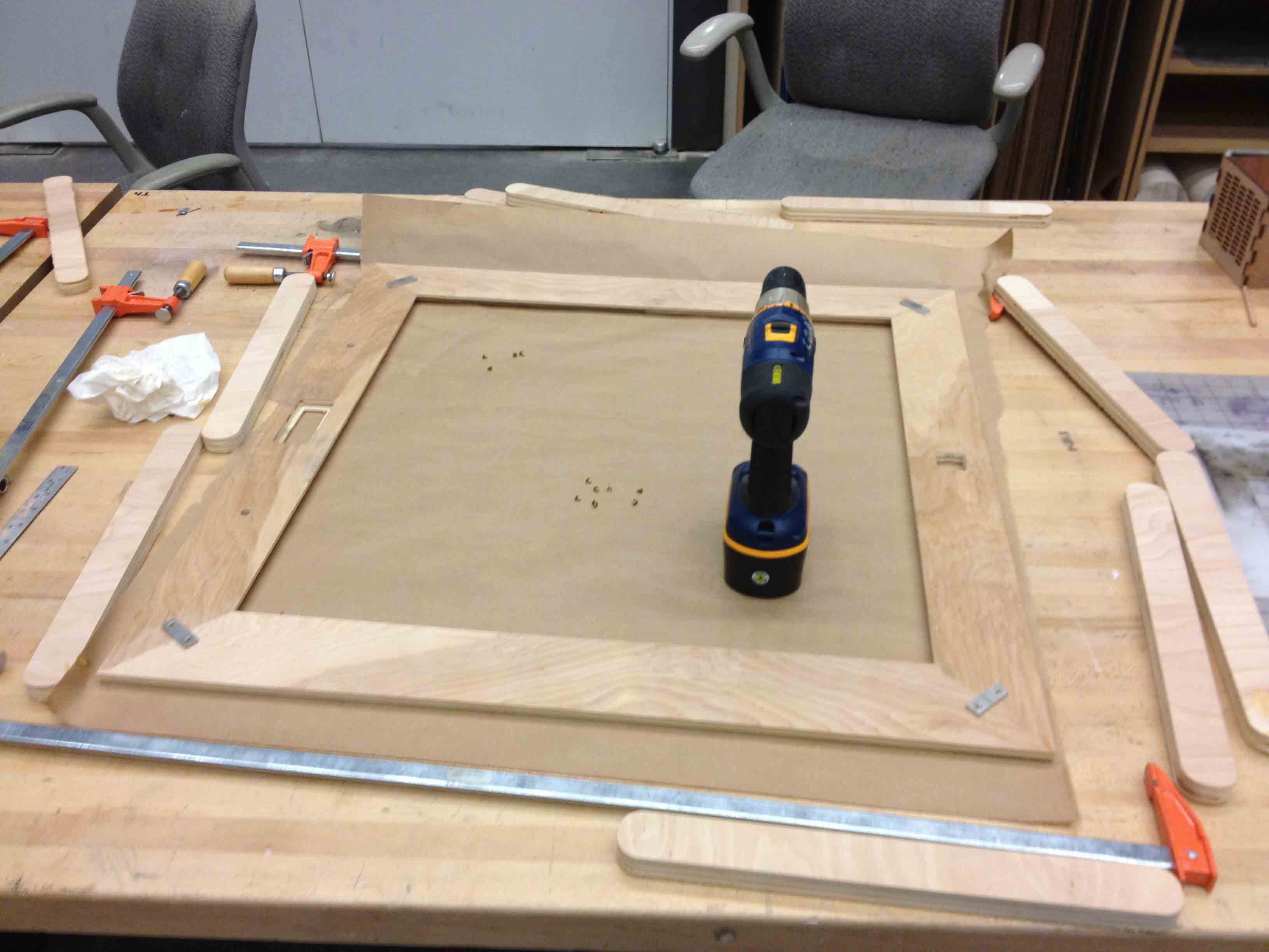
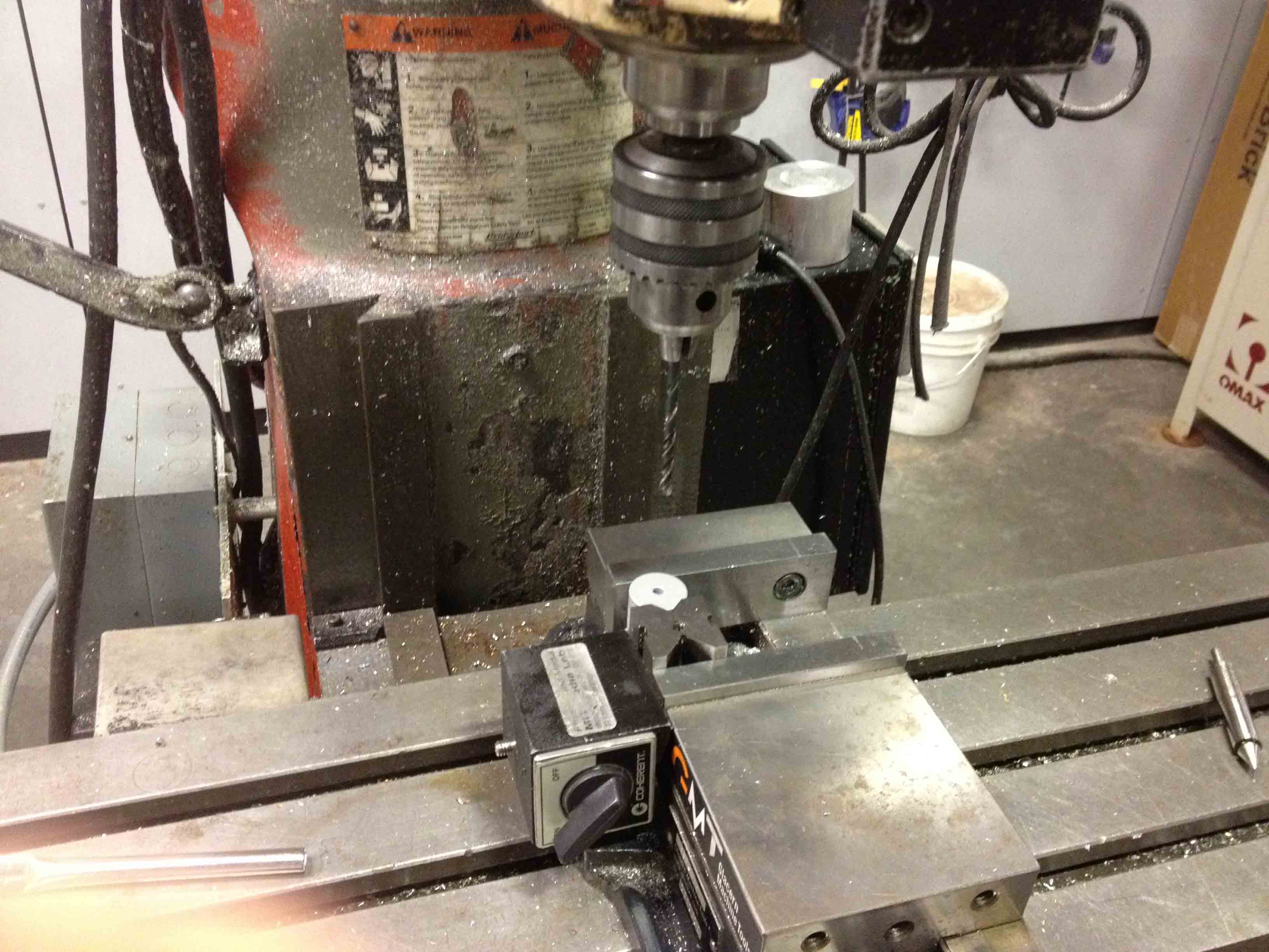
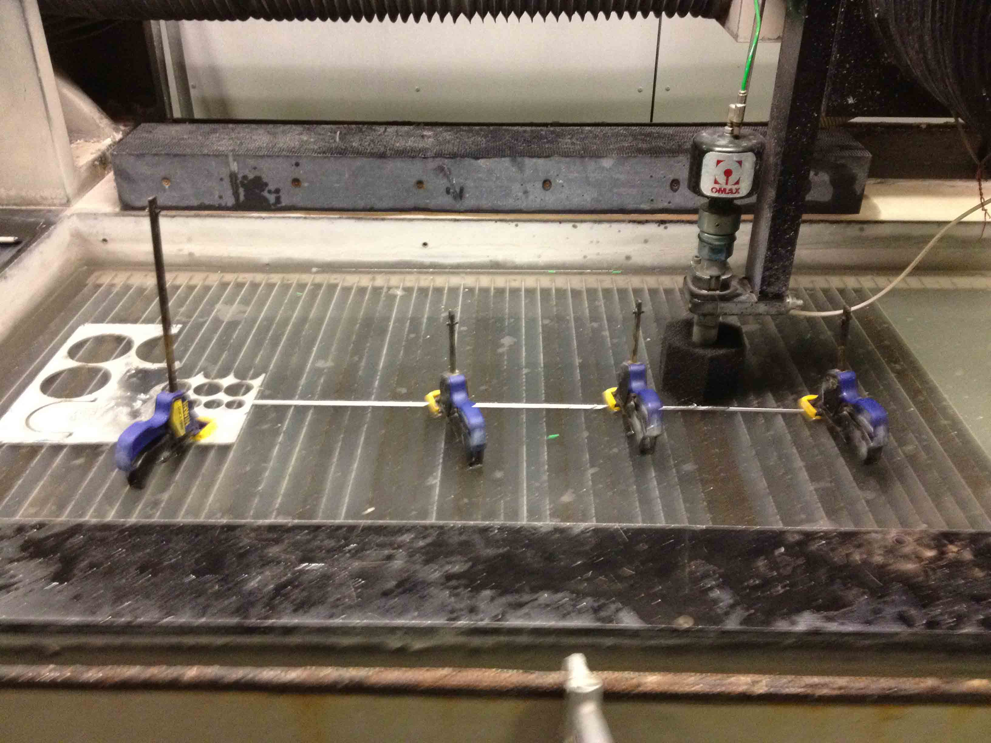
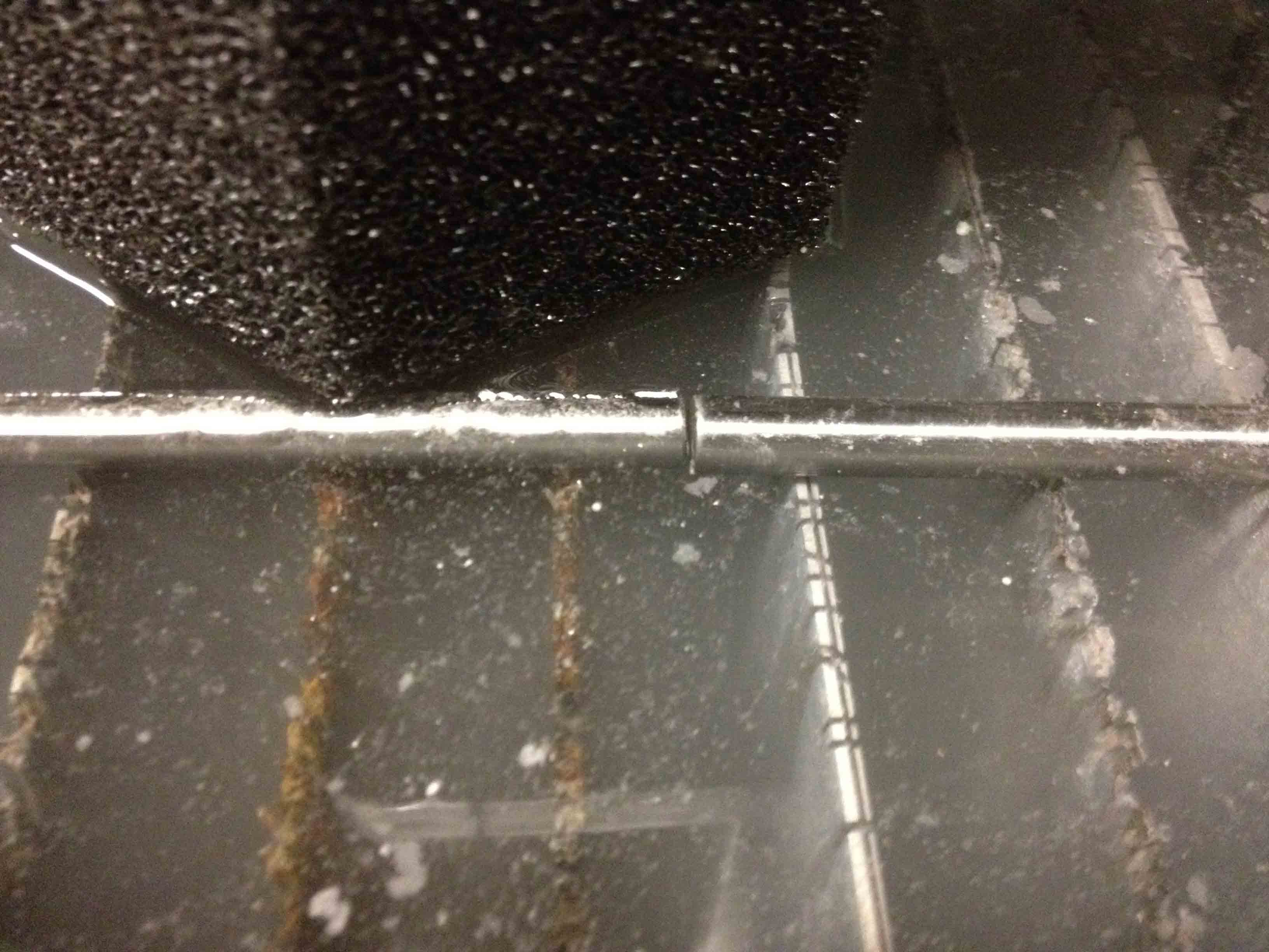
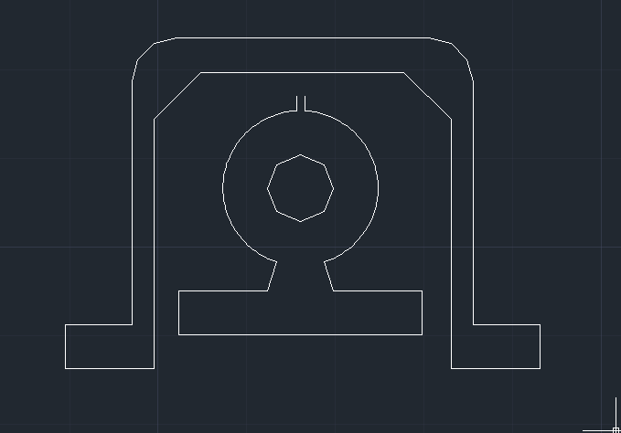
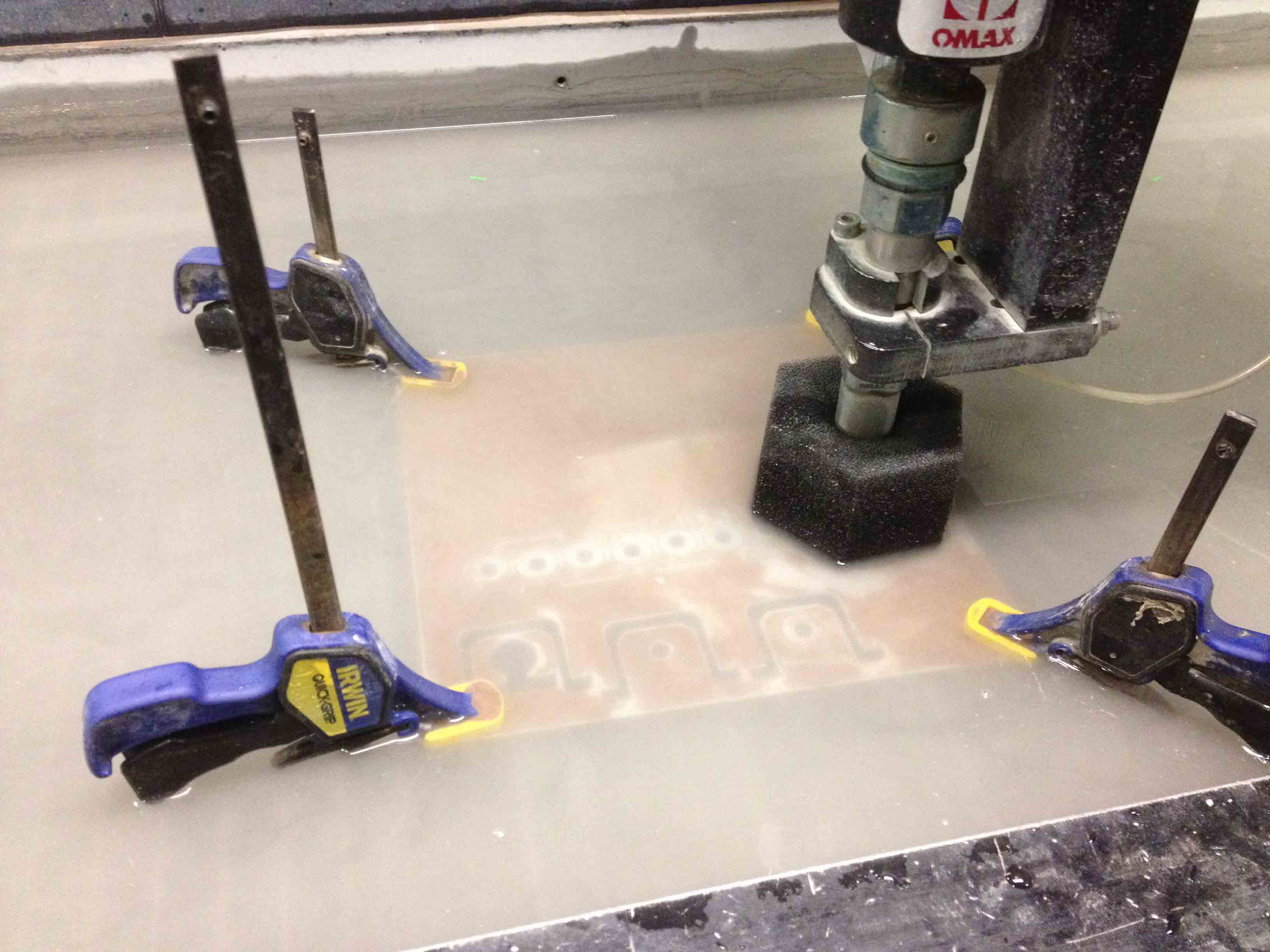
I then wood-glued them together, and strengthened the joints using some metal brackets that I custom designed and cut with the waterjet and countersinked with the drill press.
Integrating the Board and Enclosure
The clear, slotted acrylic base fits snugly into the grooves on the wooden frame, and the wired up board sits directly on top of it, with the wires sticking through the bottom. A button fits into the square hole on the right and an LCD screen fits into the rectangular hole in the middle on the left. Two LEDs fit into smaller circular holes near the LCD screen.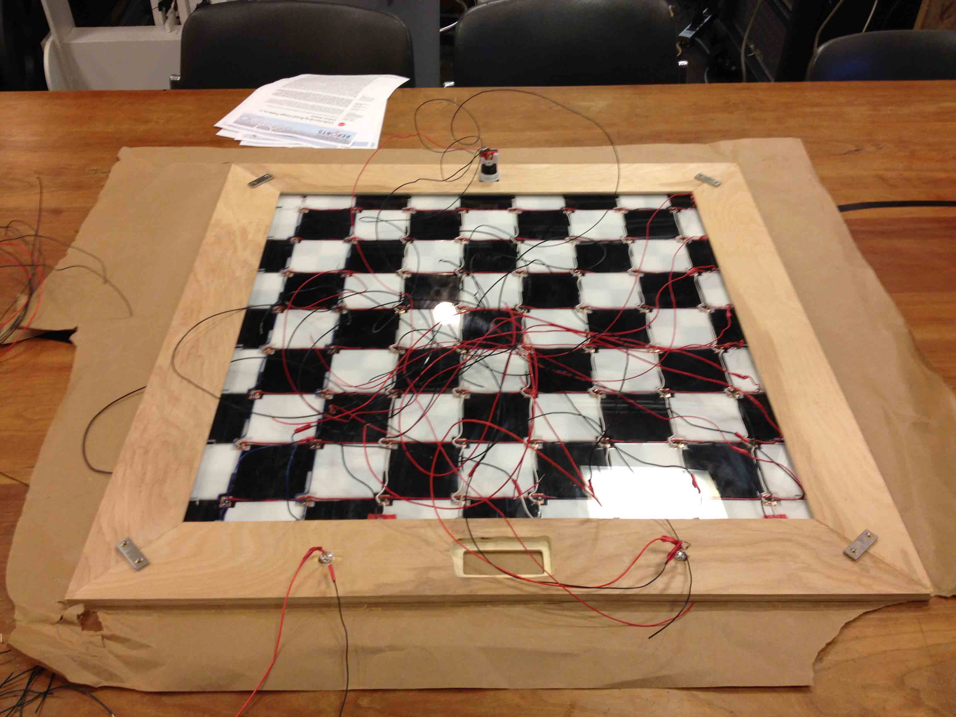
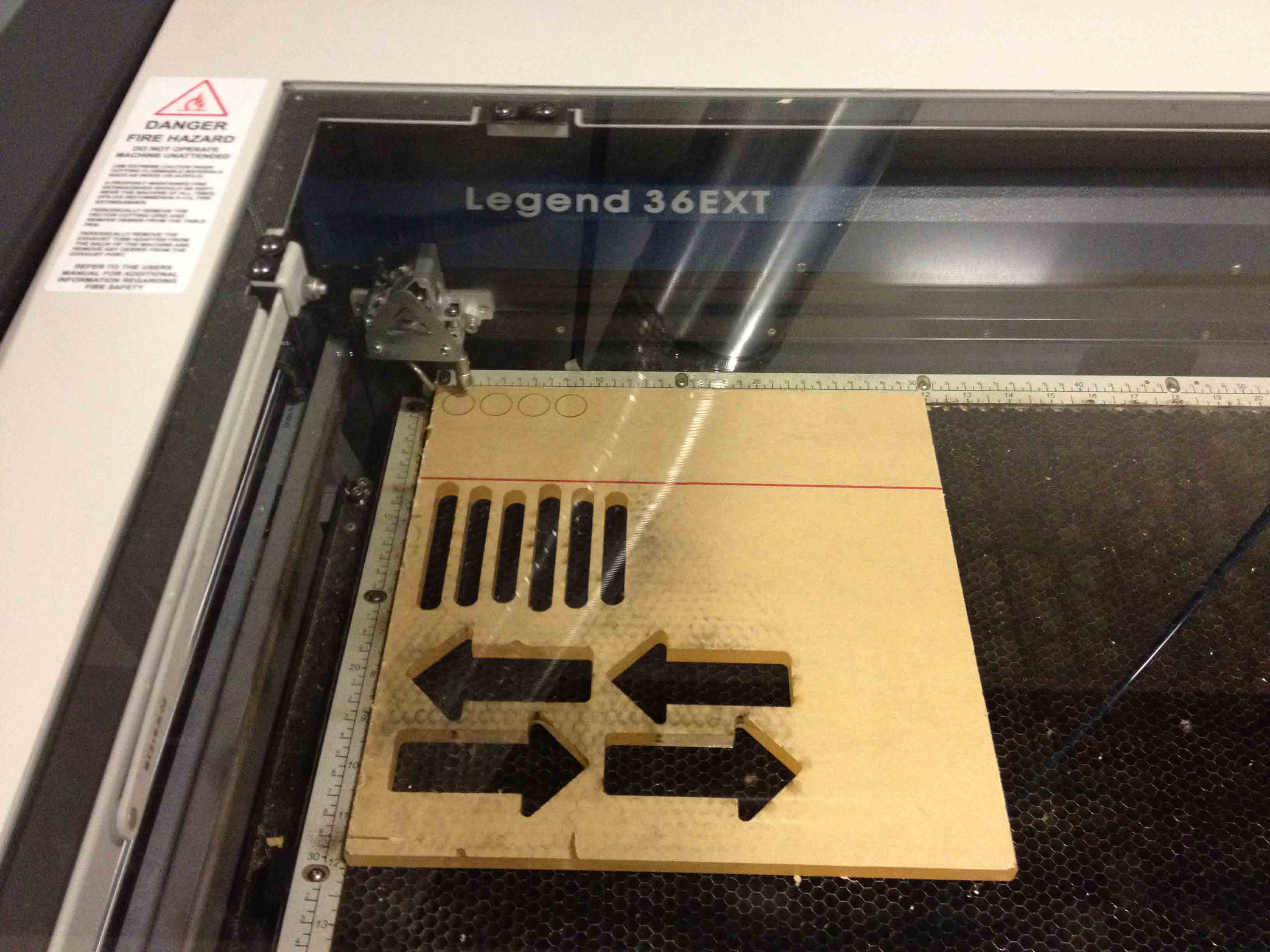
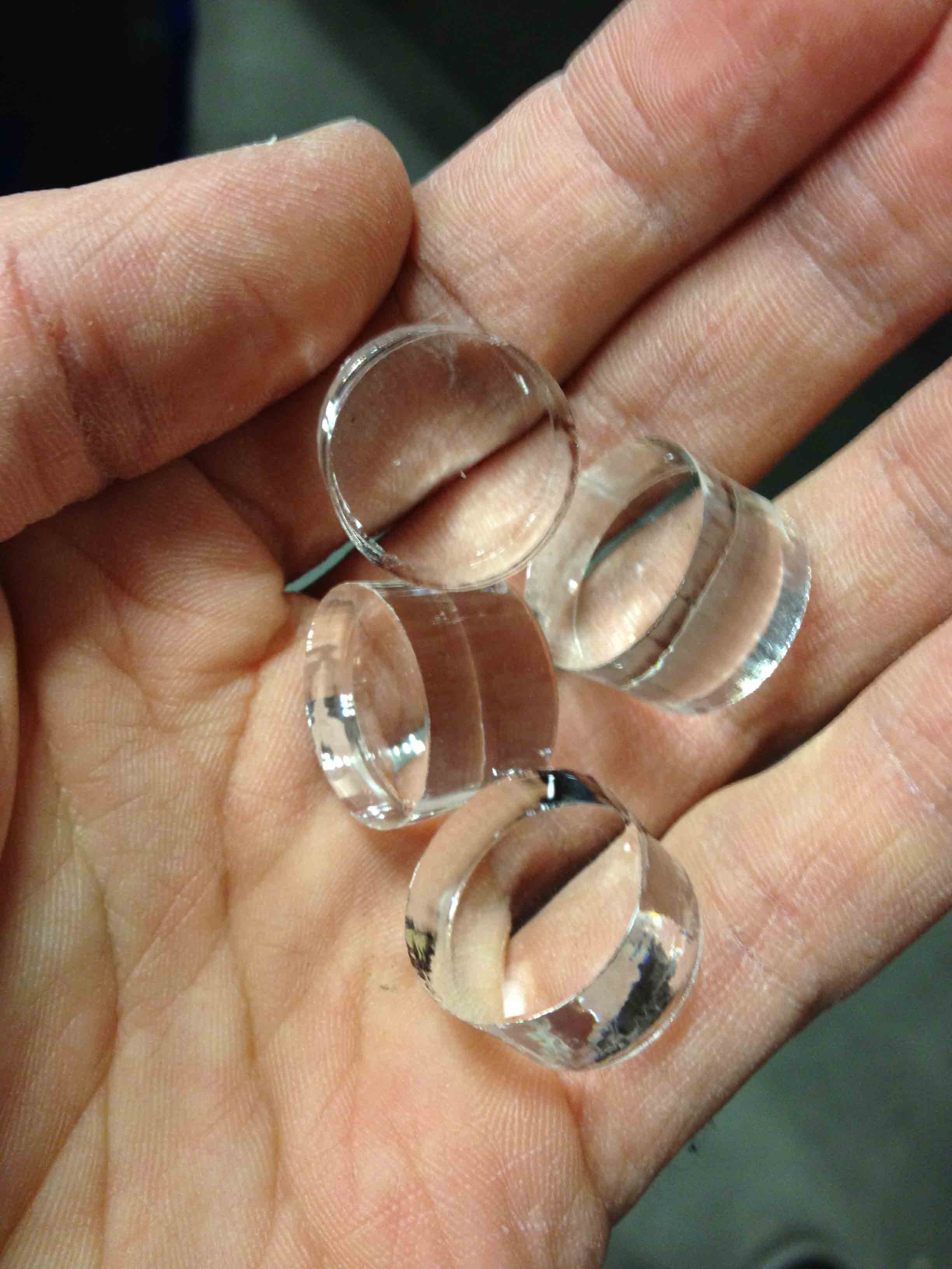
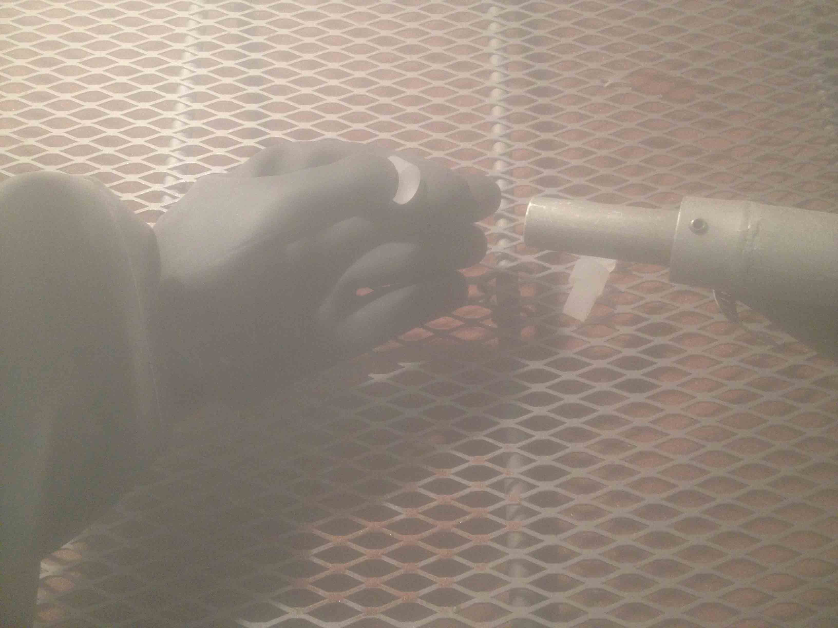
I also lasercut some small circles out of 1/2" thick clear acrylic and sandblasted them to give them a frosted look. They sit on top of the LEDs to diffuse the light for aesthetic purposes.
Making the Electronics
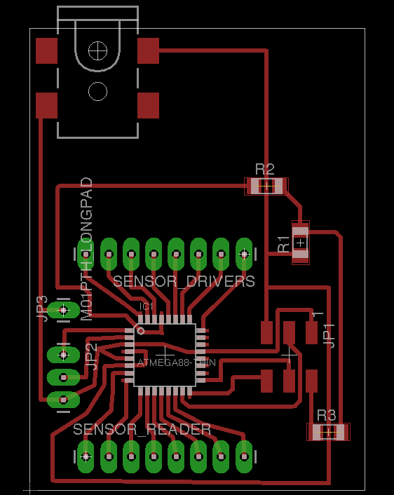
The major pain point with the electronics design was that I needed A LOT of I/O pins on my microcontroller. None of the microcontrollers we had in stock in the shop could support what I needed to do, so I set out to design a distributed, multi-processor system. I figured I could make one circuit board to monitor the hall-effect sensors, and another to handle the mechanics, LCD screen, button, LEDs, and wifi, with the two chips talking to each other via serial communication. I had designed and experimented with the board-monitoring chip and a WiFly breakout board, but this quickly got very complicated.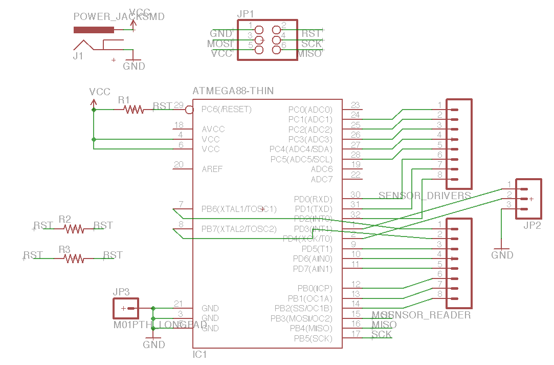
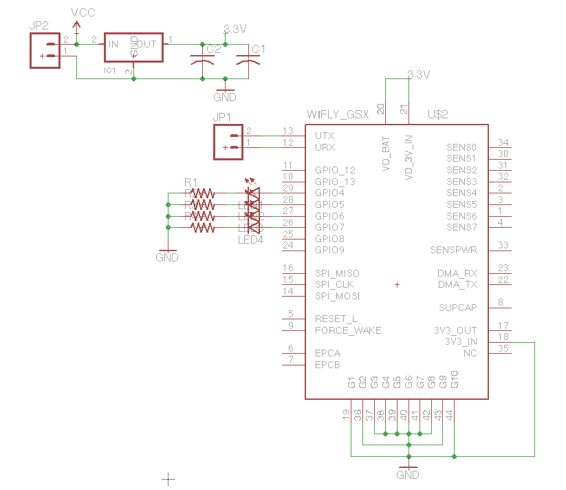
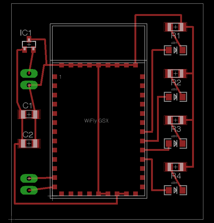
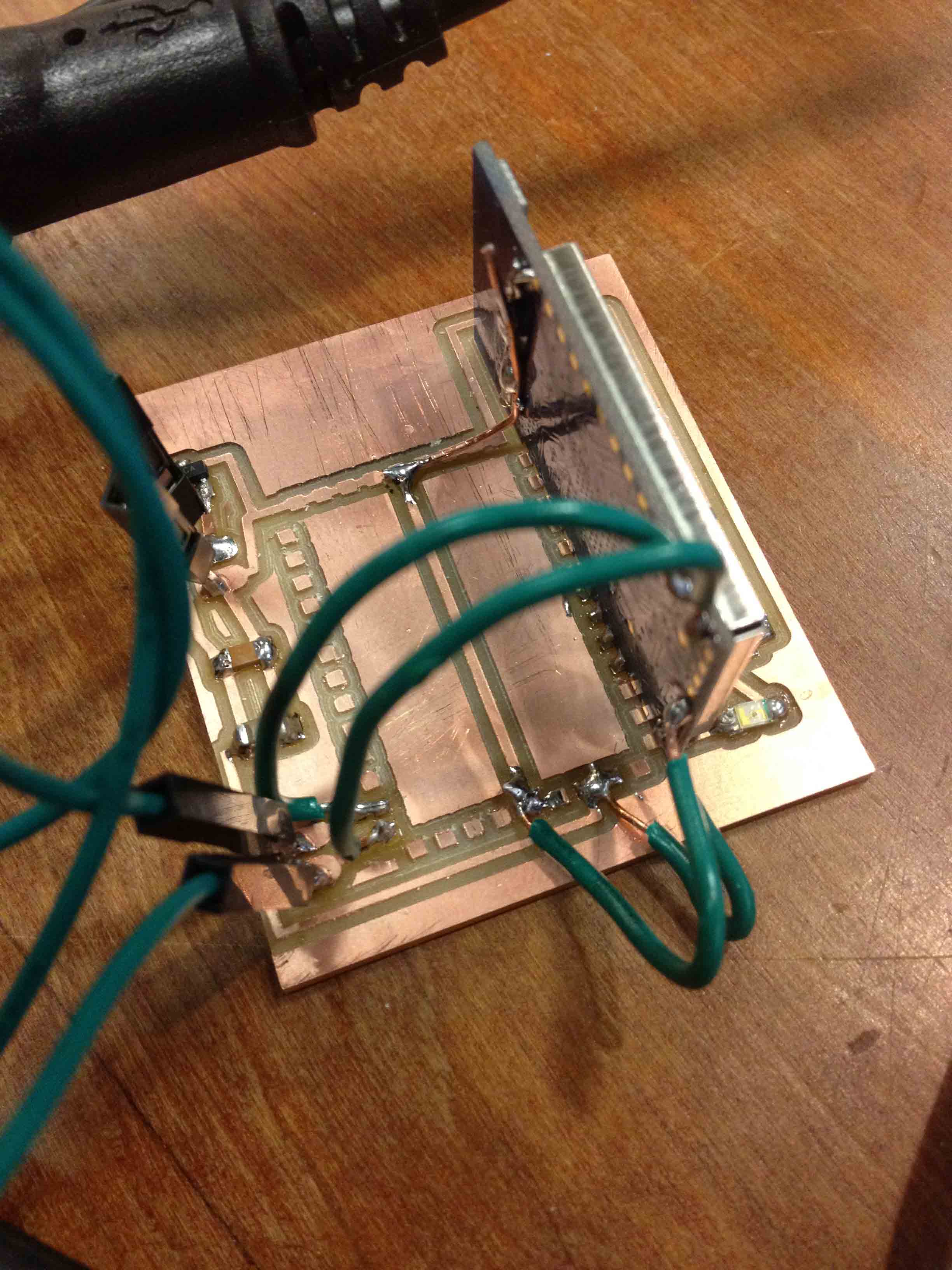
The amount of software that would have been required to drive these chips and keep them in sync was daunting, and I eventually ended up using an Arduino Mega and a WiFly shield.
Making the Machine
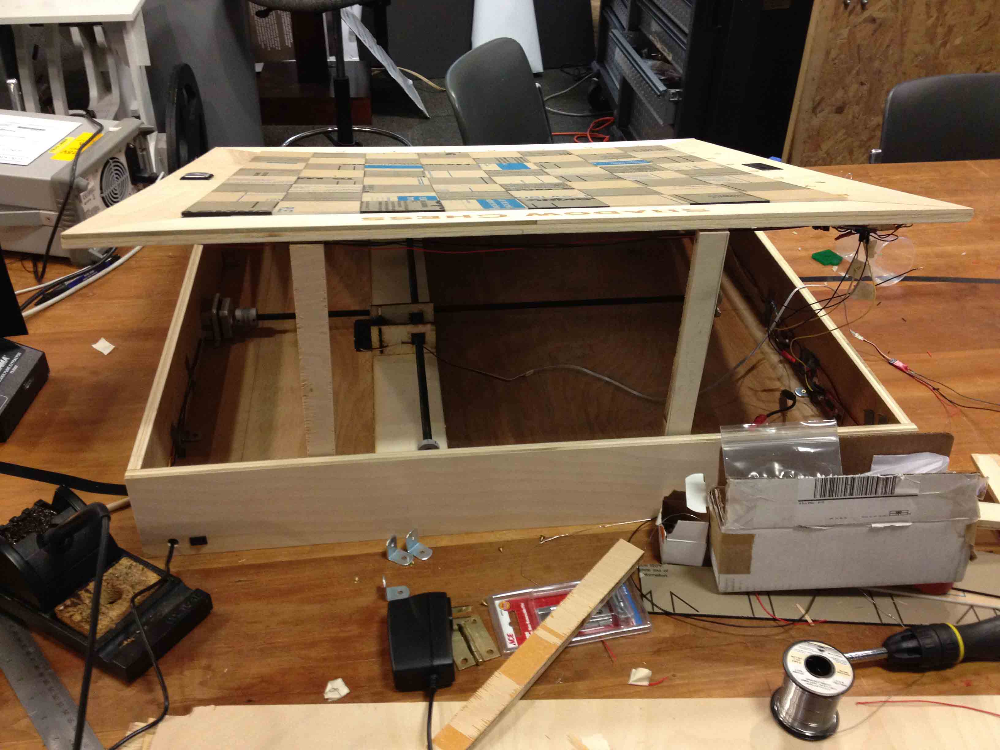
During week 14, I had designed a mechanism to move in the XY plane, consisting of two stepper motors at the outskirts of the enclosure driving intersecting cross beams using threaded rods and nuts. A loose fitting box sat at the intersection, which would be pushed around by the moving crossbeams.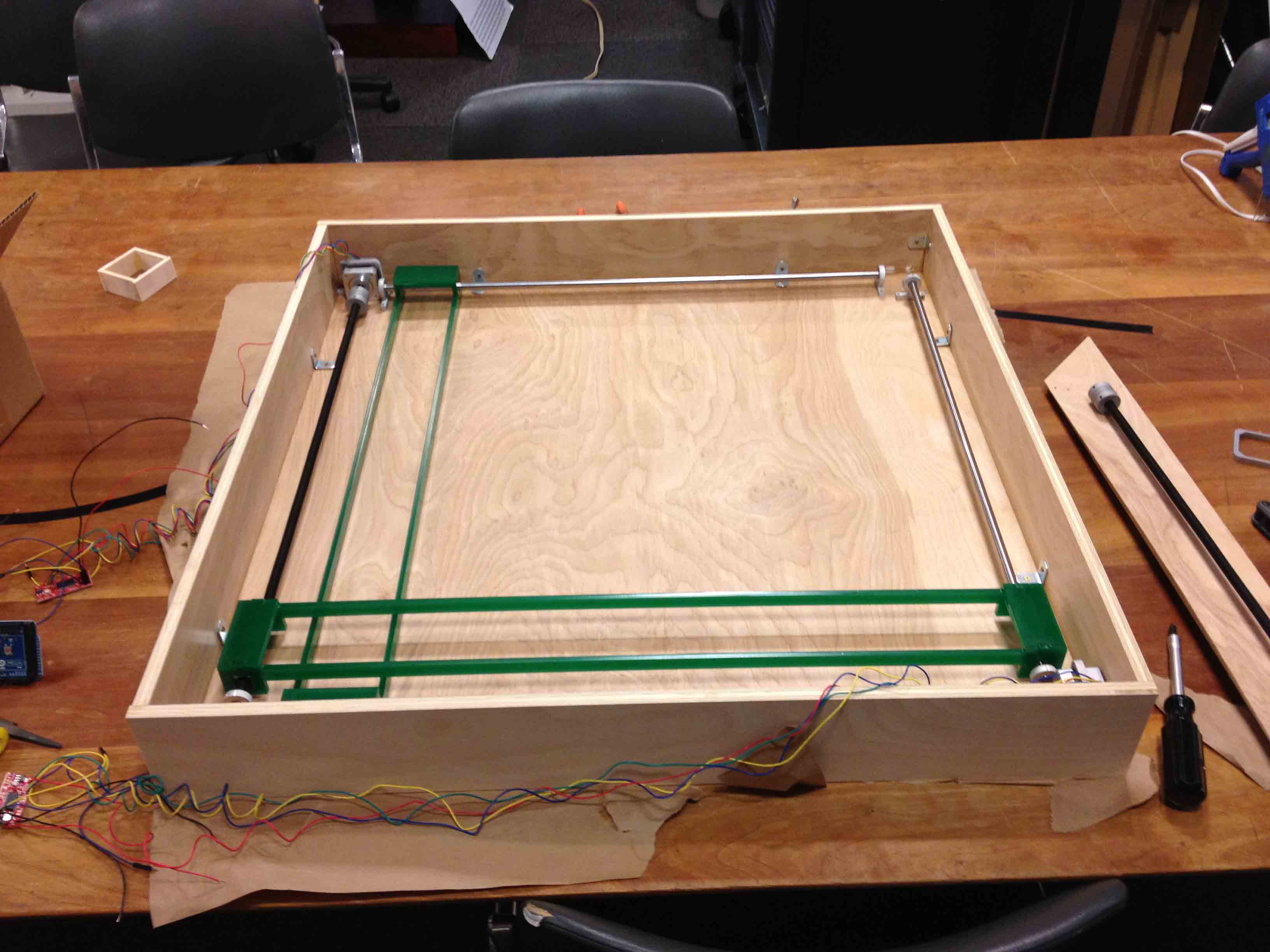
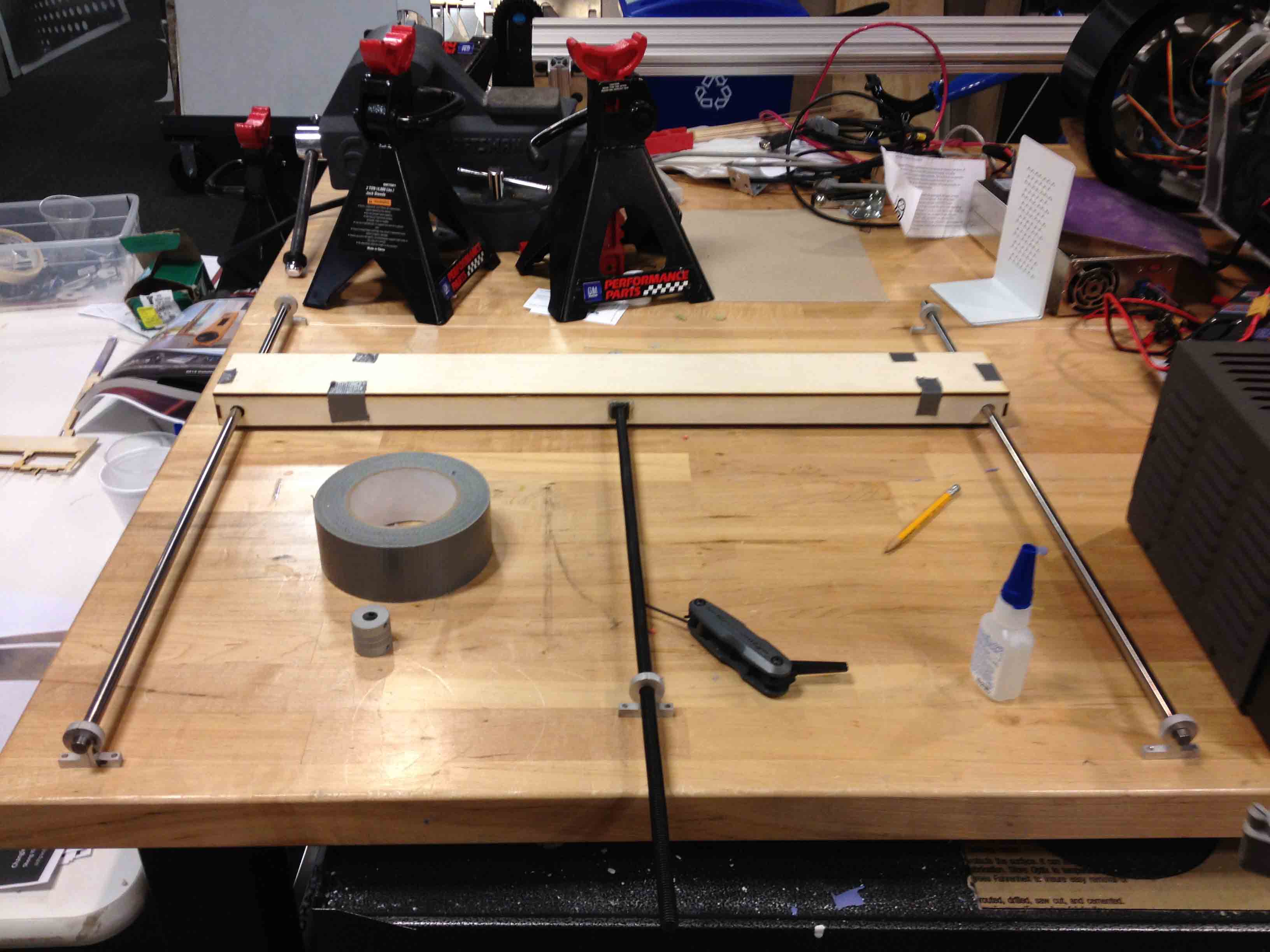
My team and I built it, but we quickly realized a flaw with this design -- because the crossbeams were so long, they could twist and deform, and had trouble pushing the box around when it was far away from the threaded rods. For the final project, I redesigned this mechanism so that the X-Stage threaded rod sits in the middle of the box, with shafts on either side so that it has less room to deform. The Y-Stage motor sits on top of the X-Stage, which moves the magnet back and forth.
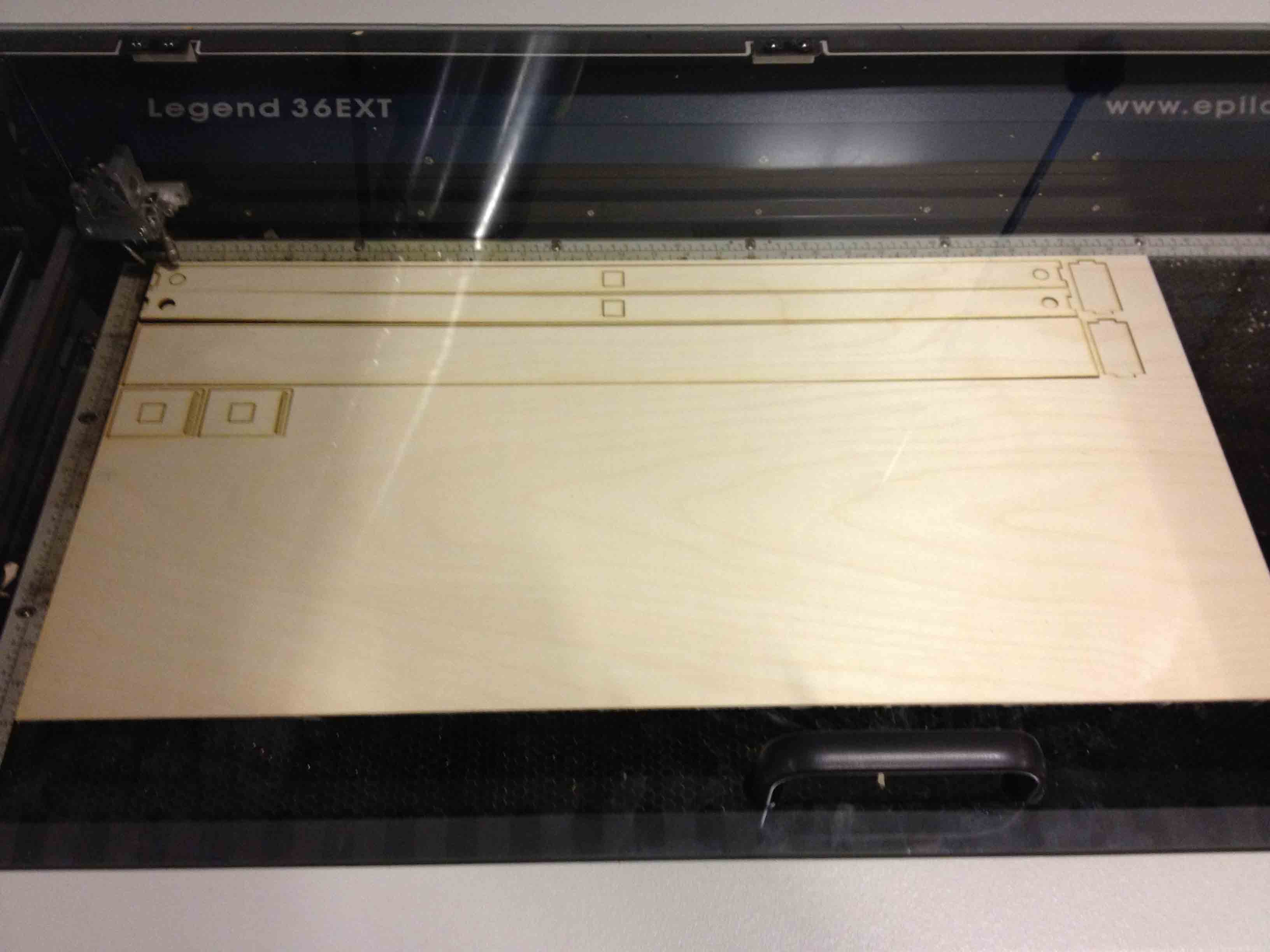
As described in week 14, I drilled out the smaller bore holes of the shaft couplings so that the stepper motors would fit, cut the shafts and rods down to size, and designed and cut out brackets with the waterjet to secure the motors and shafts.
I designed the crossbeams with AutoCAD and lasercut them out of 1/8" thick plywood (we had used acrylic before, but I wanted them to be less bend-y this time). I glued in the nuts, threaded them on the the rods, and glued the structure together.
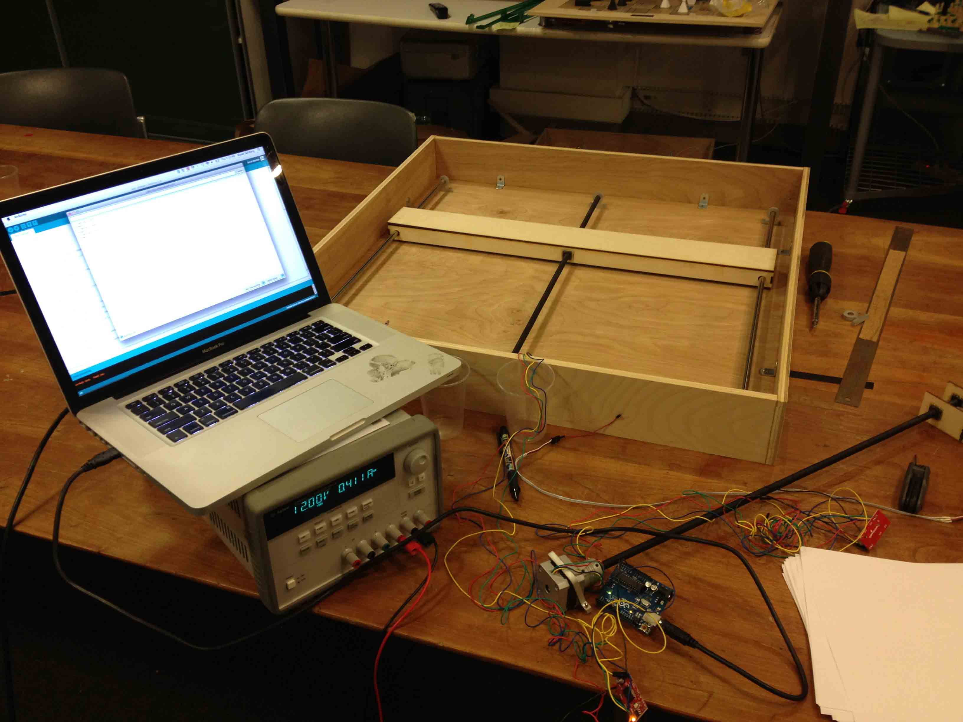
This video demonstrates the crossbeams moving in the X direction.
This one shows it moving in the X and Y directions.
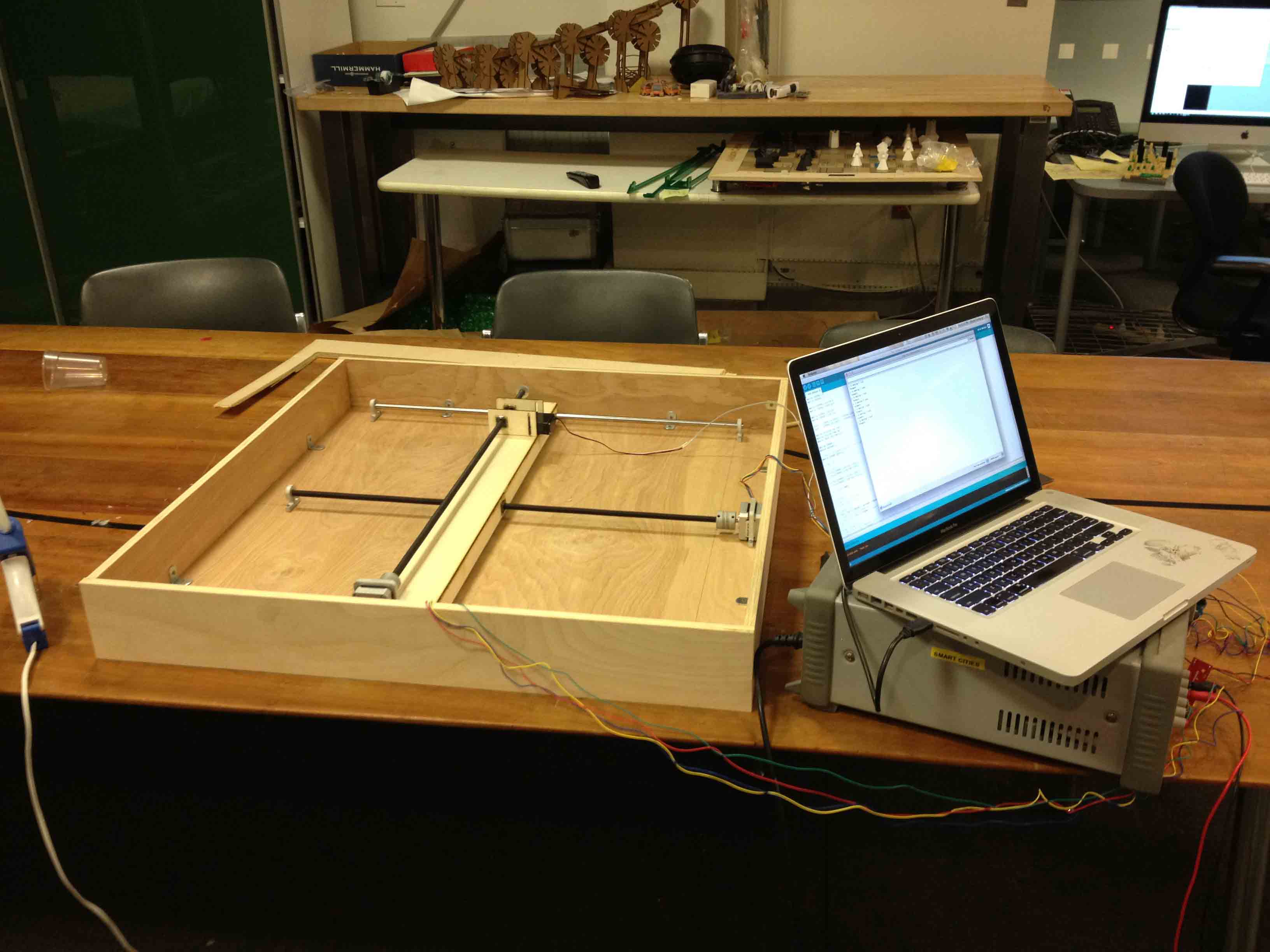
This one shows it moving in the X and Y directions inside the full enclosure.
The magnet moves up and down using a servo motor to attach and detach from the pieces above.
Once the top is closed, the magnet can move pieces around, as demonstrated here by the queen.
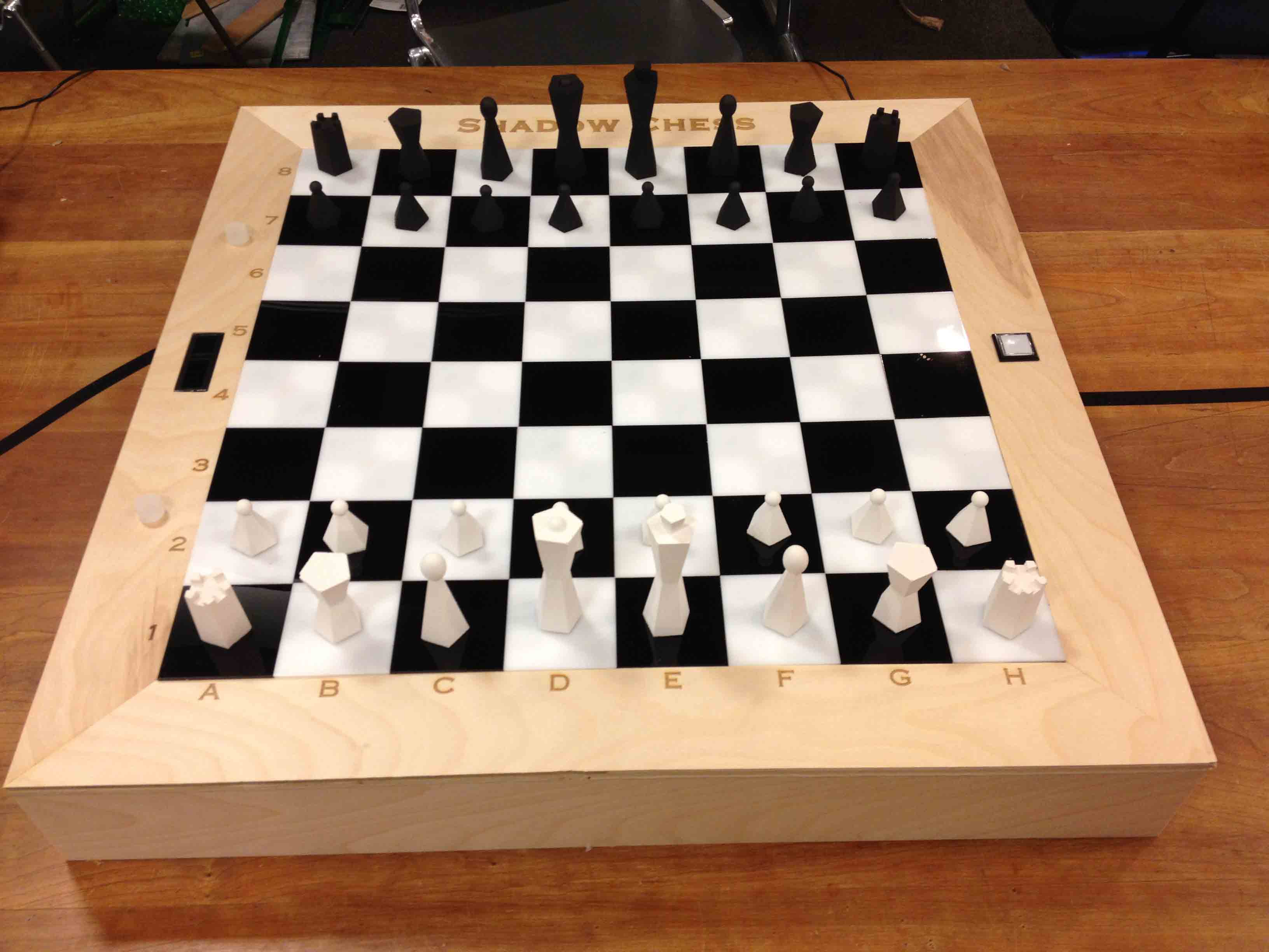
Once the protective paper was removed from the board, it looked a lot nicer!
And here is a pawn moving as part of an actual game.
Limitations
There are two main limitations with this design. The first deals with the sensing system and the second revolves around the mechanical design.The sensing system I designed employs a magnetic sensor under each square and a magnet in each piece. This structure, however, only tells me if there is a piece on a square or not -- it doesn't tell me WHICH piece is on the square. This works for the most part because chess always starts out in a known arrangement, and only one piece ever moves at a time (except for capturing or castling). Thus, when one of the sensors says a piece has been removed from it, and another says a piece has been placed on top of it, we can infer that the same piece has been moved from the former square to the latter. To capture a piece, a player has to perform a very specific gesture so that the software can recognize it as a capture -- he first has to pick up the piece to be moved, then remove the piece to be captured, then place the moved piece down where the captured piece used to be. This obviously is prone to user error though, and castling is pretty tricky to recognize as well. The ideal solution would be to embed RFID tags in each piece (as I originally intended) and put an RFID reader under each square so we could get both location and identity. This direction, however, was prohibitively expensive.
The other limitation is in the mechanical design. Even though the final version I came up with is much better than the first one we made in week 14, its still not perfect. Its not nearly accurate or fast enough to use in a real game. This is mainly because I coupled the stepper motors directly to the threaded rods for simplicity, but this set up means the rods can only turn as fast as the motors can turn, which is not incredibly fast. I'll need to experiment with gearing systems and drive belts to make it more reliable and user-friendly in the future.
Design Files:
- wifly_shield.sch
- wifly_shield.brd
- wifly: top.png
- wifly: holes.png
- wifly: outline.png
- wifi_test.ino
- beam_v2.dwg
- crossbeamsv3.dwg
- large_holes.png
- large_top.png
- large_outline.png
- squares--v2.dwg
- top.png
- holes.png
- outline.png
- chess_pieces_v2.3dm
- lettering.psd
- numbering.psd
- title.psd
- shadow_chess.ino
- real-chess-with-friends.zip