This week we learned about output devices such as LED arrays, LCDs, video, motors, speakers, and piezos. For my project, I decided to focus on servo motors.
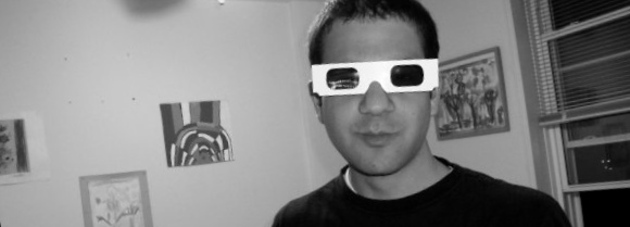
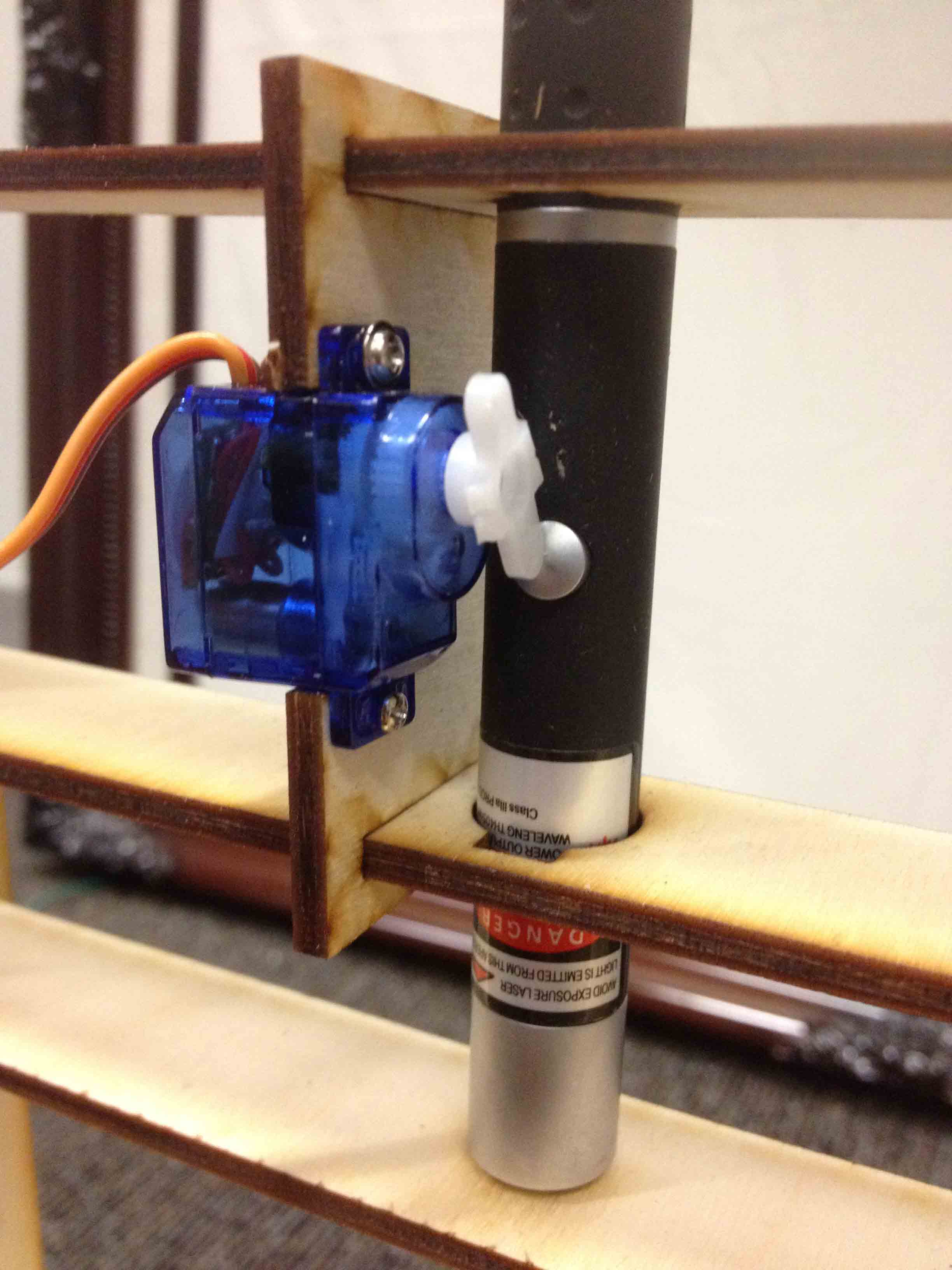
A few years ago, I made a serendipitous discovery that blue laser light super charges phosphorescent material, and framed a piece of glow in the dark fabric so that I could hang it on my wall and draw on it with my blue laser. Since then, I've been wanting to make a rig for my laser that automatically draws pictures for me by rotating a mirror to redirect the beam. So I finally did it!
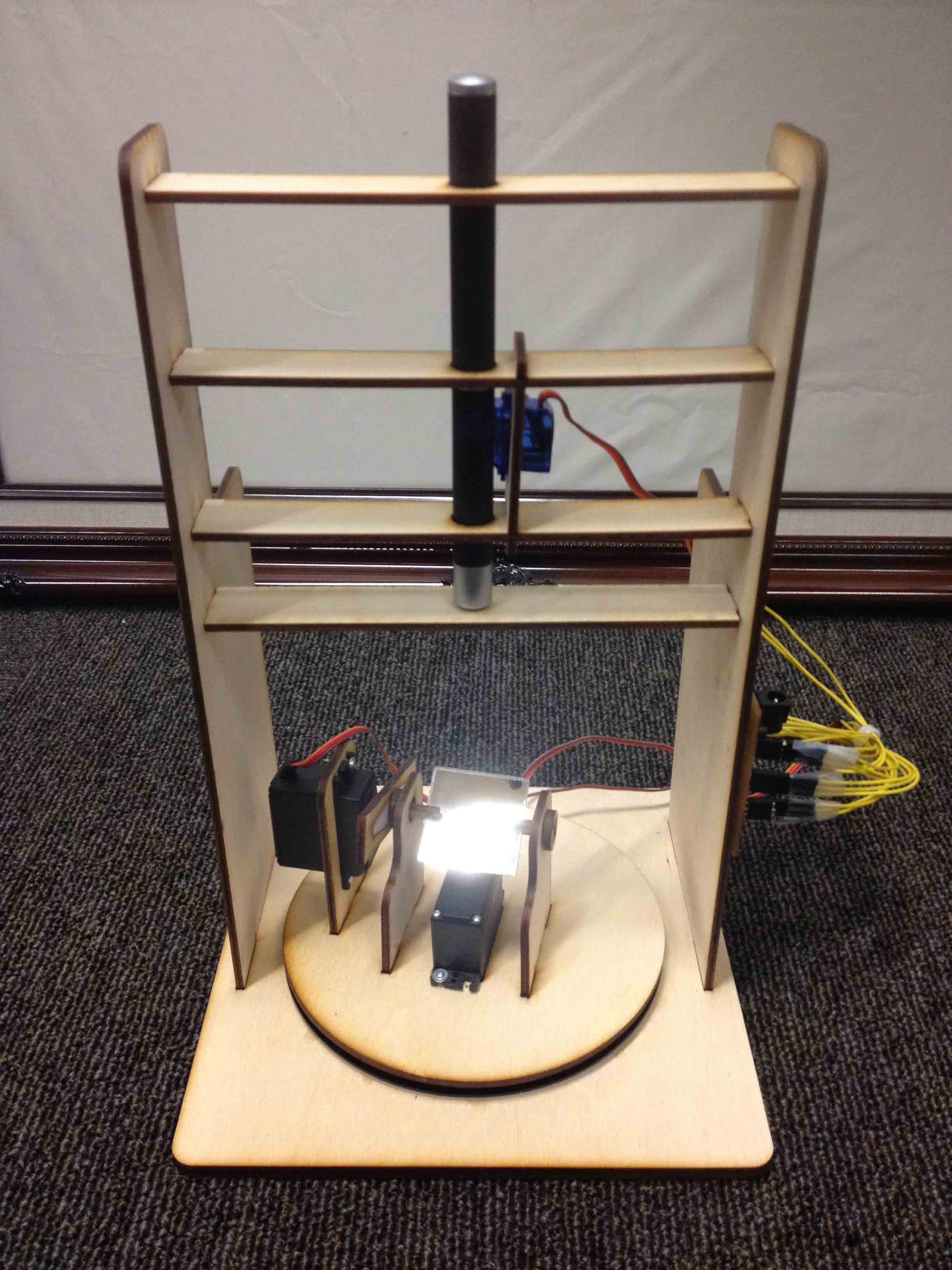
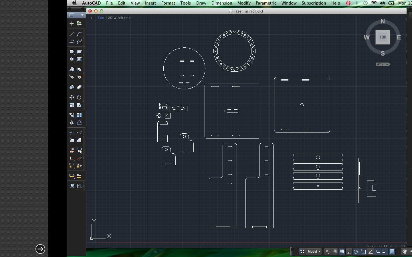
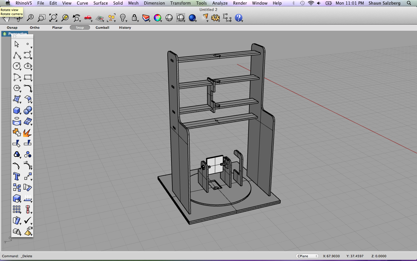
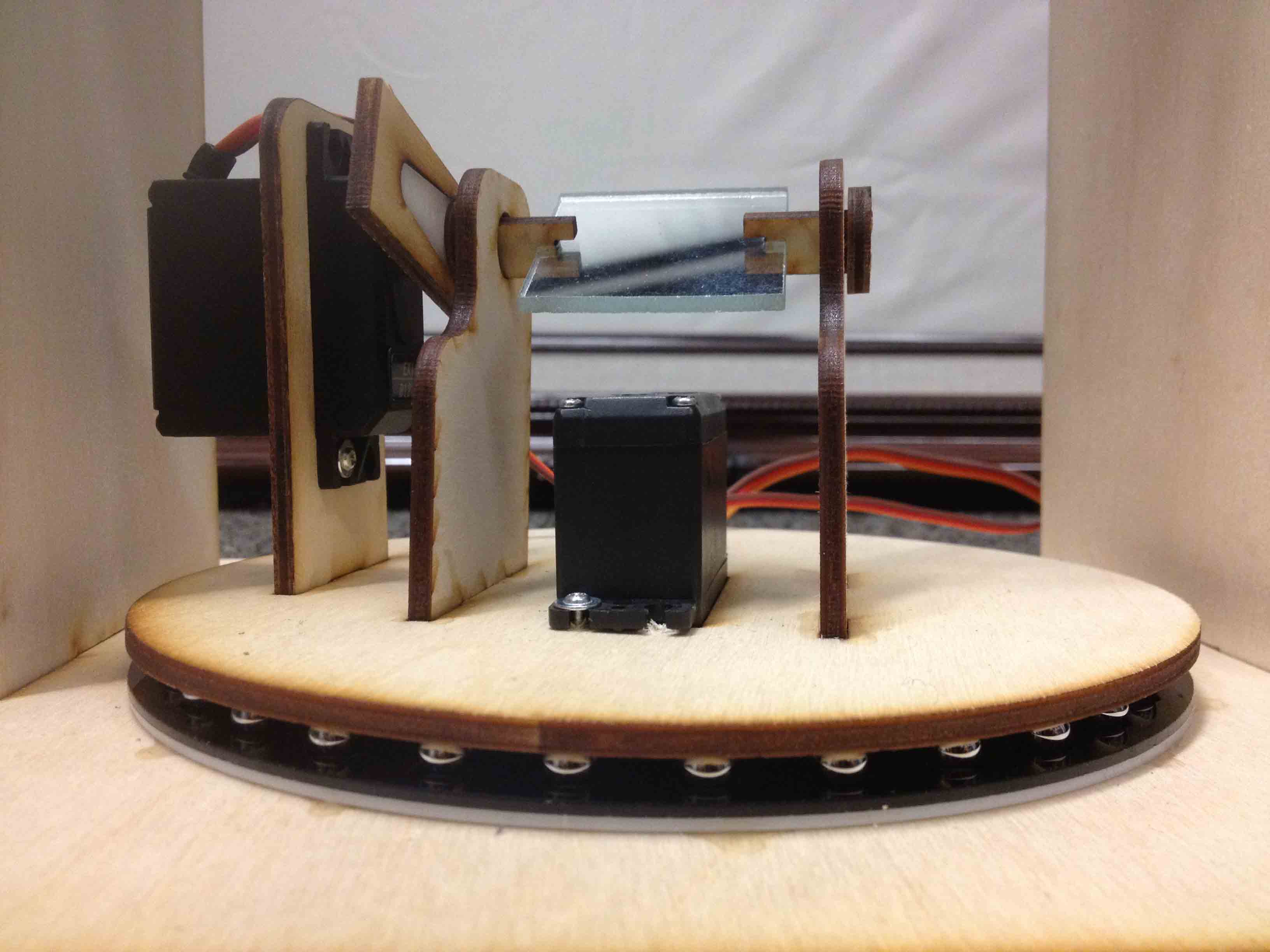
First I designed the rig in AutoCAD and laser cut it out of 1/8" thick birch plywood. I modeled it in Rhino first to make sure everything fit together.
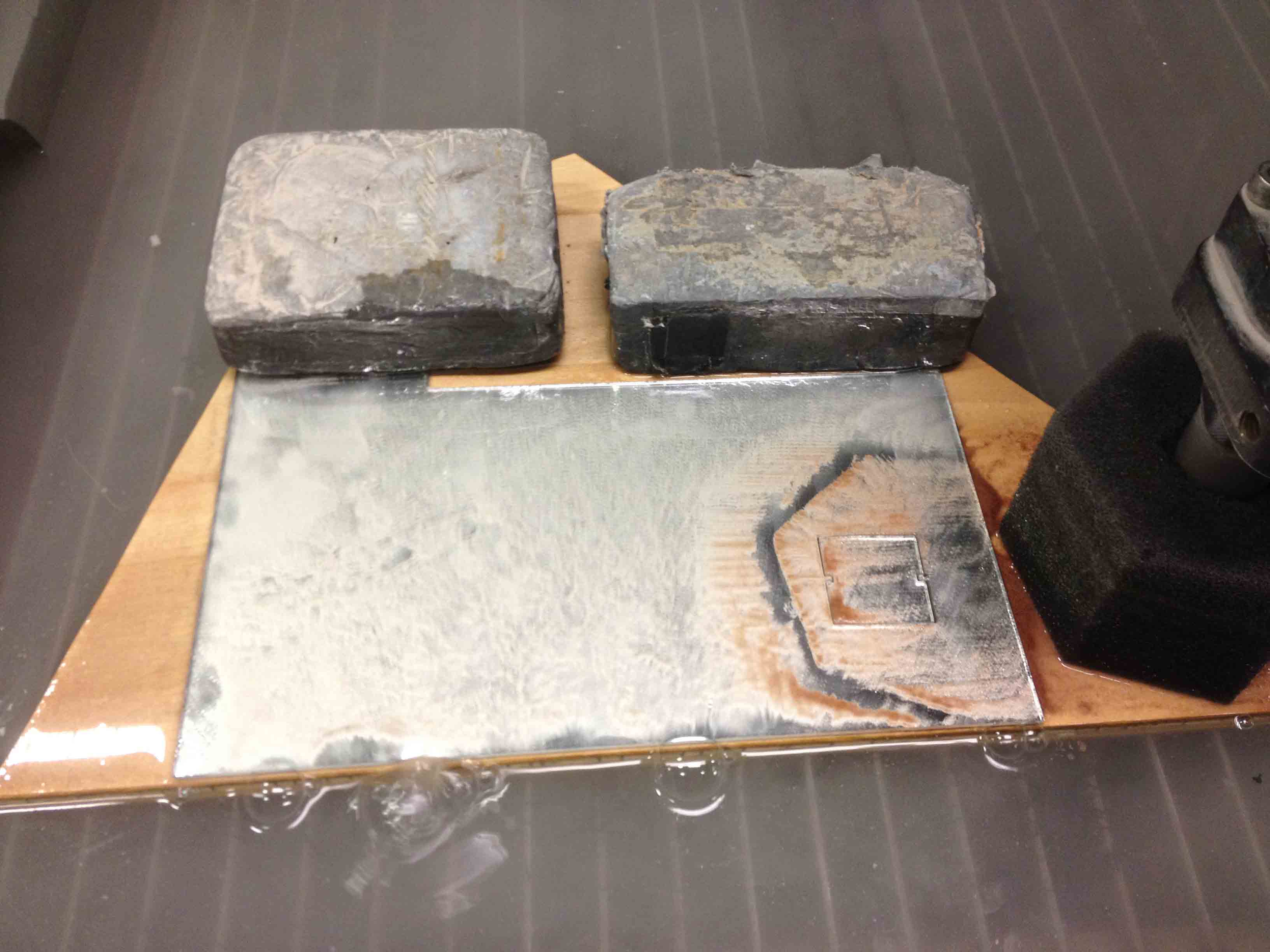
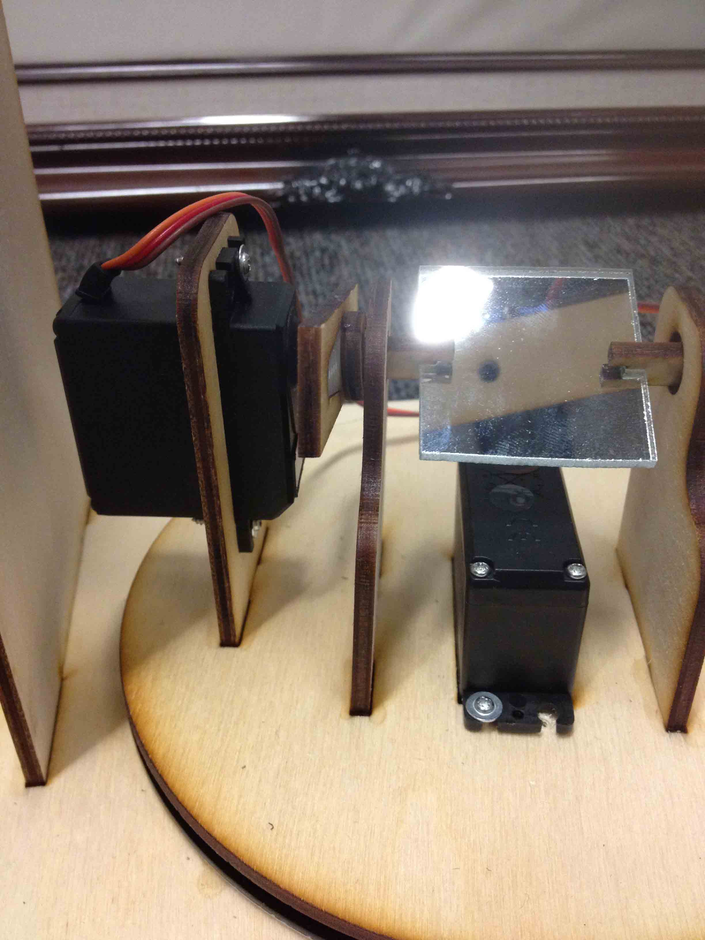
I also designed and cut out the mirror using the waterjet. Thanks to Jin Joo who gave me the left over mirror she had from her project a few weeks ago! She also showed me the right way to cut out a brittle material like mirror on the waterjet without cracking it. As she mentions in her post, the tricks are to 1) put a support material like wood underneath the mirror, 2) use weights instead of clamps to hold it down, and 3) use the "brittle material" setting on the waterjet.
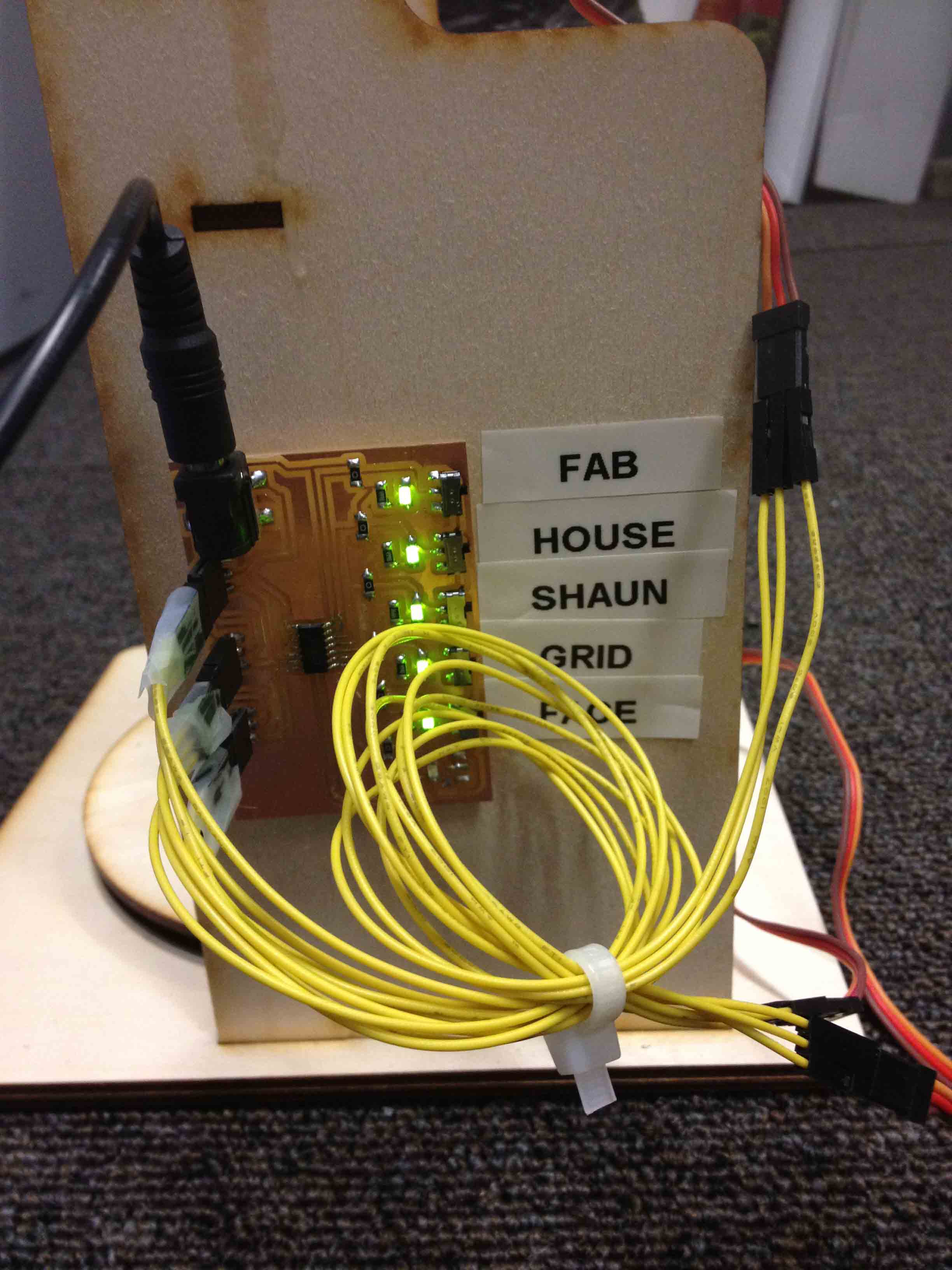
Finally, I designed the servo motor controller in Eagle, milled it out on the Modela, and stuffed it. Its essentially an attiny44 with ports to plug the three motors into. I also added some switches on the side so users can toggle on and off which pictures the device cycles through when drawing.
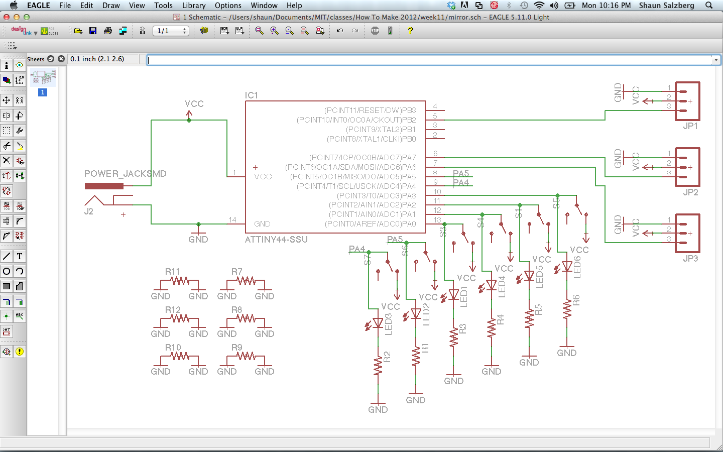
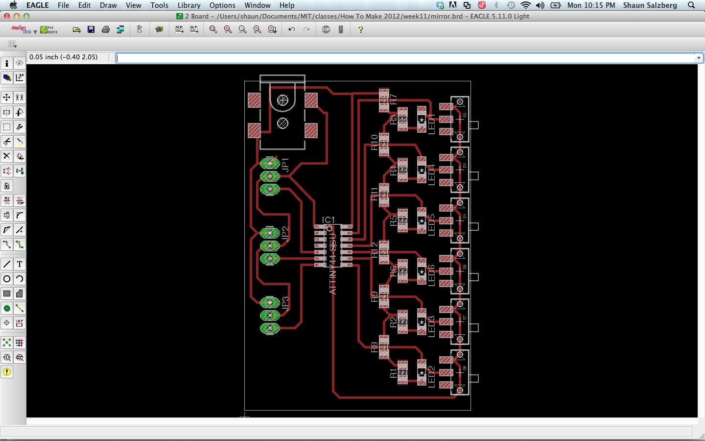
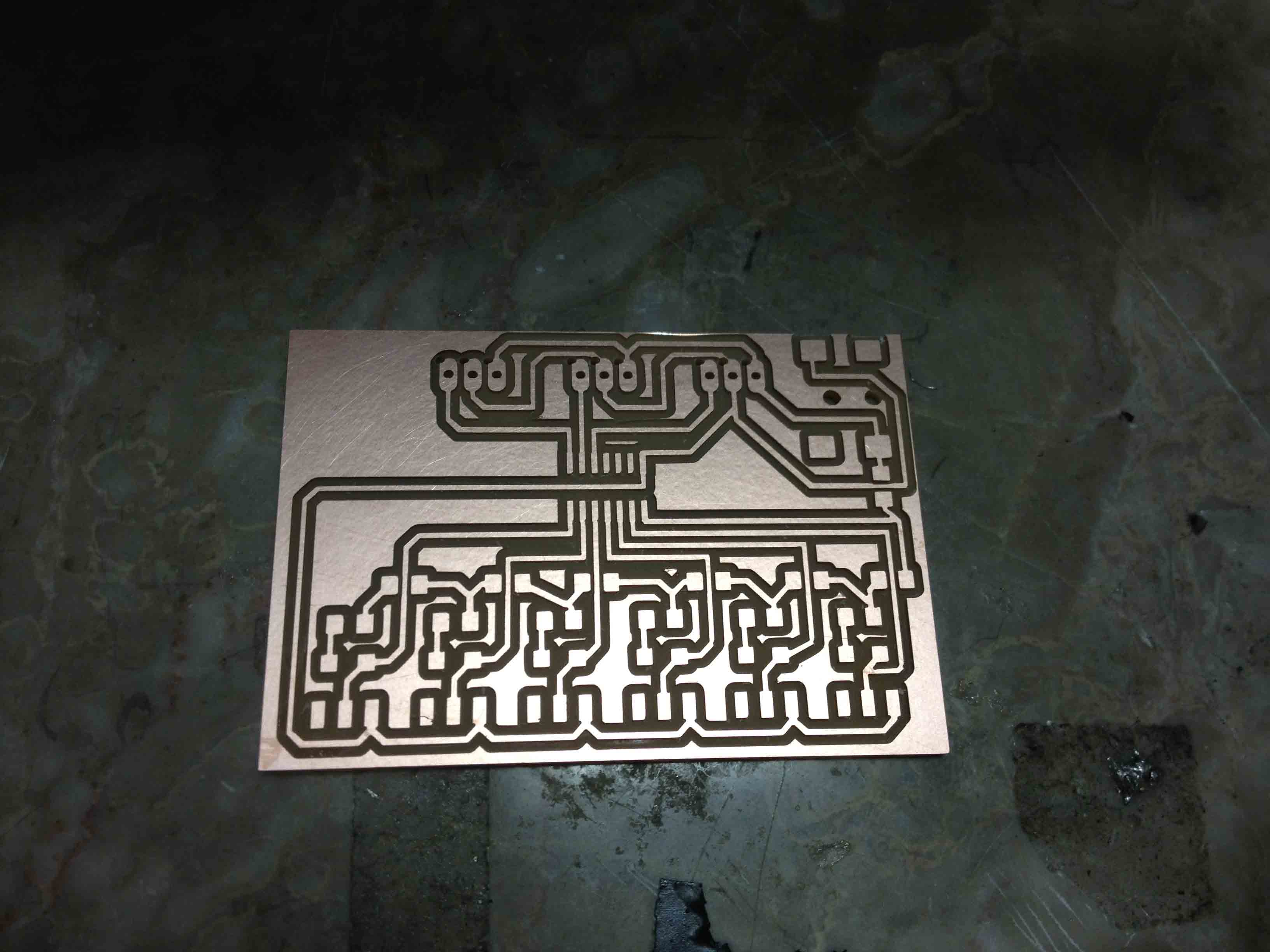
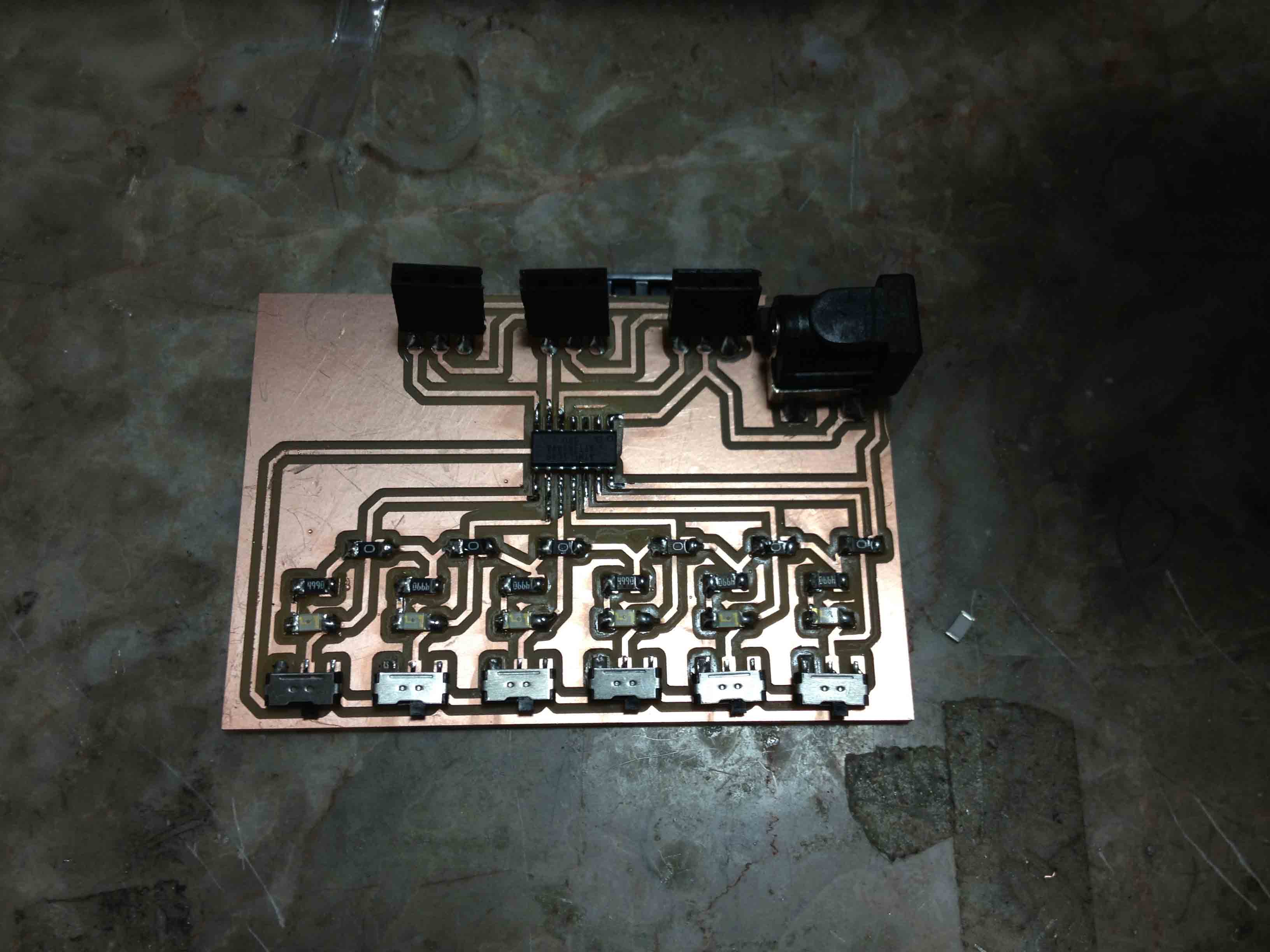
I actually learned a valuable lesson while doing this: you can't trust the Eagle parts library from Sparkfun. I had used the Power Jack component in the Sparkfun library and spent a long time milling the board out only to find that their schematic reverses power and ground! And it took a long time and a few fried boards to figure this out. Eventually I just switched VCC and GND in my schematic, and it was only a minor nuisance to mill the board again.
I used Loctite420 to glue the wood pieces together, and screwed the servos into position. I also added some ball bearings underneath the X stage motor to give it a bit more stability.
I wrote the code for the device within the Arduino environment, and used an Arduino Uno as an ISP again since my FabISP key never really worked so well.
I wrapped up the servo control in functions like "moveTo(x,y)", "laserOn()", "laserOff()" so that instructions to draw look something like:
The standard Servo library for Arduino doesn't work with AVRs, so I tried to use the SoftwareServo library instead. It mostly worked with the attiny44 out of the box, but I had to make some modifications to the library to get it to work with the PB pins. I basically added another parameter to the "attach" function to indicate if the specified pin is part of PORTA or PORTB, and modified how the pin is referenced throughout the code. The fully modified library can be downloaded at the bottom of the page.
And here it is!
You may notice that its not exactly perfect. The positioning isn't perfectly accurate and the image is distorted because I'm using a rotating mirror to project an image onto a flat plane (I should have thought that through better before). Also, because I'm using servo motors which have gears inside, they can only move so fast and so far, giving me a very small spatial and temporal resolution. The spatial resolution is about 40x17 and it can only move at a rate of about one point per half second. Not terrible for a week long project though. While building this, I actually heard of an awesome device called a Galvo, which is used in industrial laser scanning machines. They consist of X stage and Y stage mirrors hooked up to electromagnets such that they can be moved really quickly and with really fine resolution. Definitely going to buy one of those soon and build a version two of this thing.
Design Files: