
This week we learned how to use the laser and vinyl cutters, and were tasked with using one of them to create a press fit construction kit (pieces that fit together like legos or k'nex). For my project, I decided to make a press fit marble track construction kit. Below is a video of a simple track that I made.
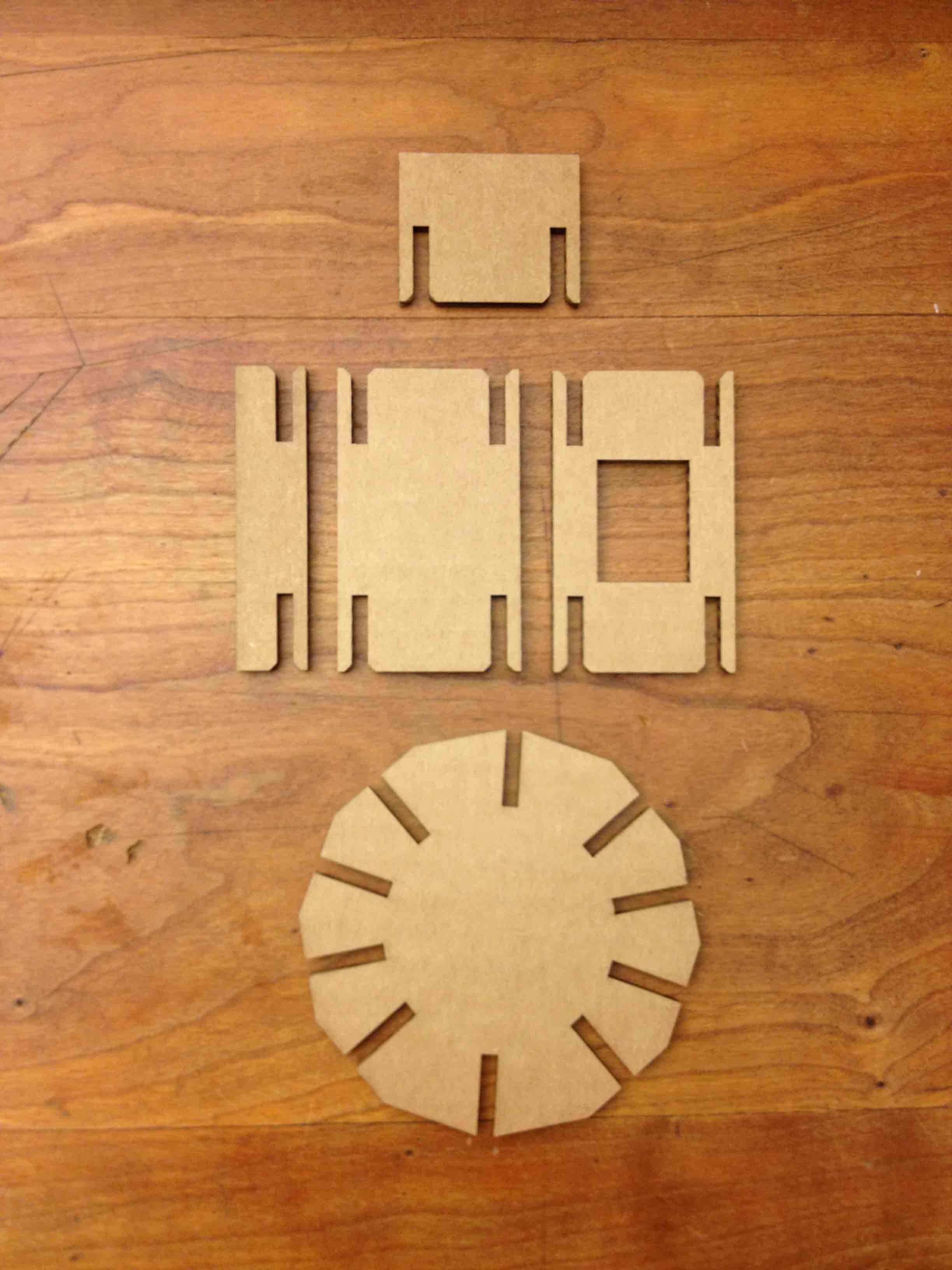
The basic pieces of the kit are the track, wall, angled connector (wheel), hole, stand, and scaffolding.
Even though I didn't plan for it, I figured out ways to connect these basic pieces in non-standard ways to do interesting things. For example, using two wheels, a track, and a track stop, I was able to make a ball collector with a release mechanism, as shown below.
I also experimented a bit with different functionalities that I could give the tracks, and settled upon a piece that I've been calling the "flip flop". Using a rotating T-shaped wall, the flip flop diverts the marbles down alternating paths. Below is a video of it in action.
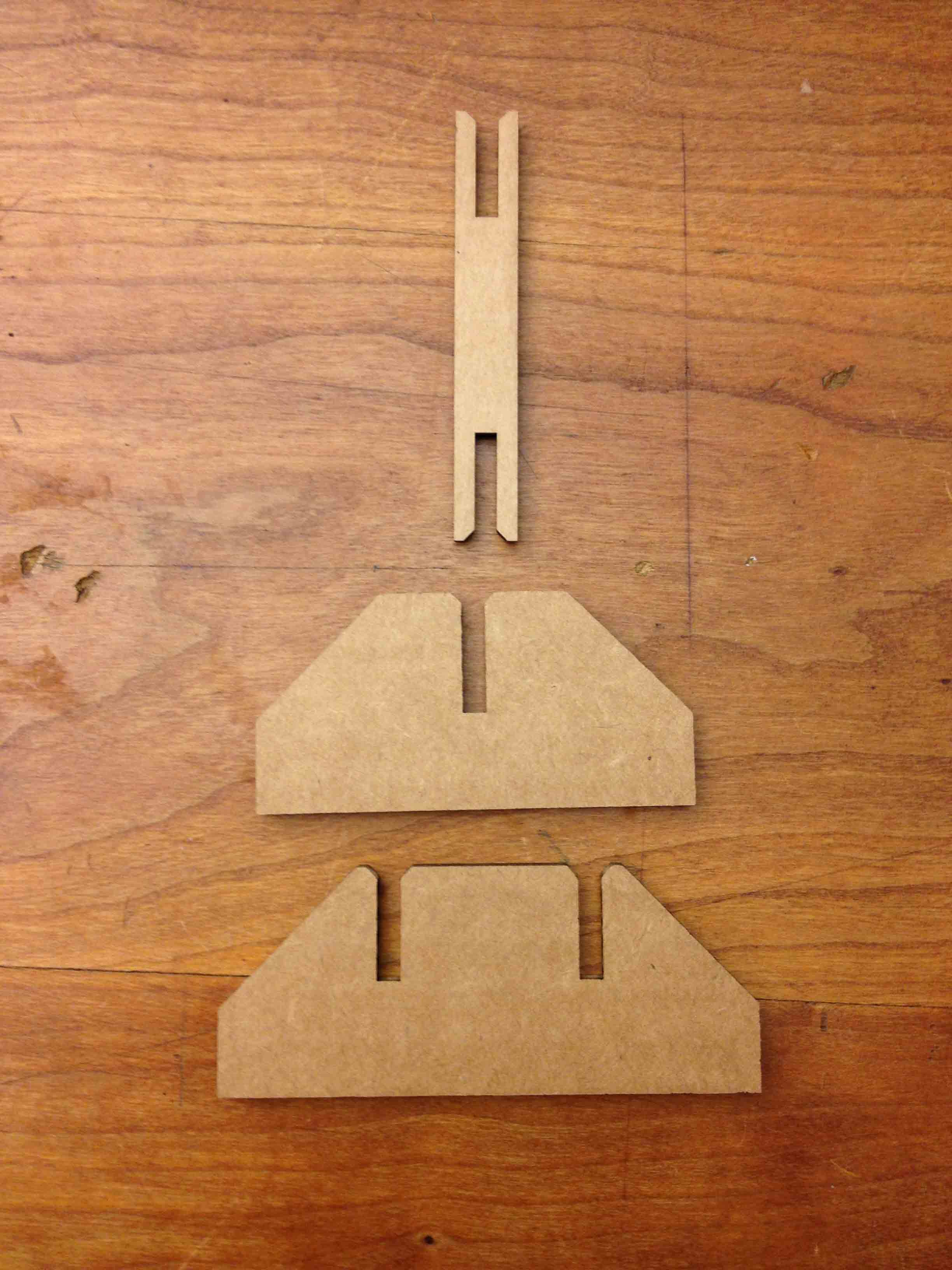
The flip flop is made from a few separate pieces, as shown below, including a corner piece that was necessary to re-angle the track correctly after the marble passes through the flip flop.
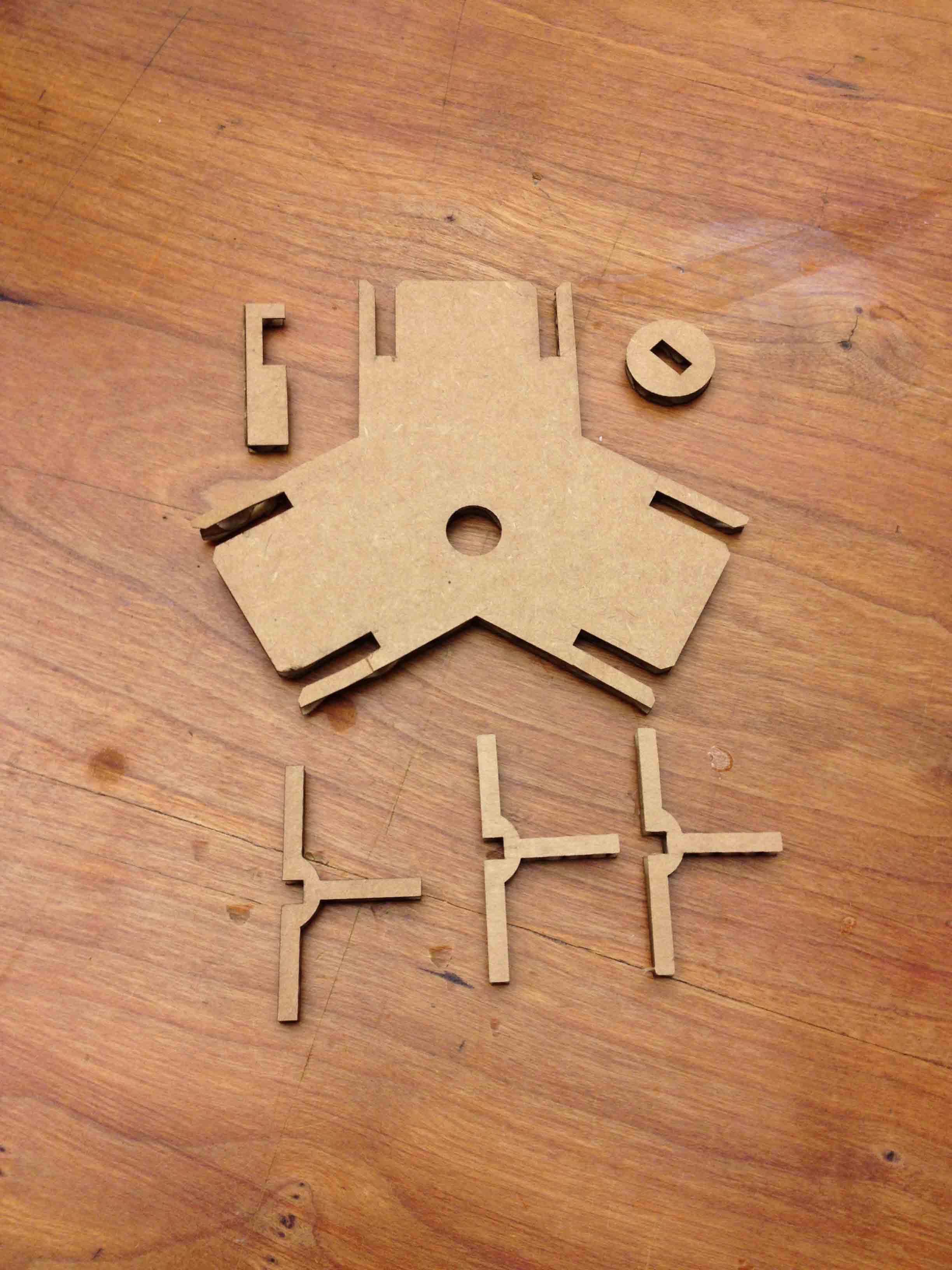
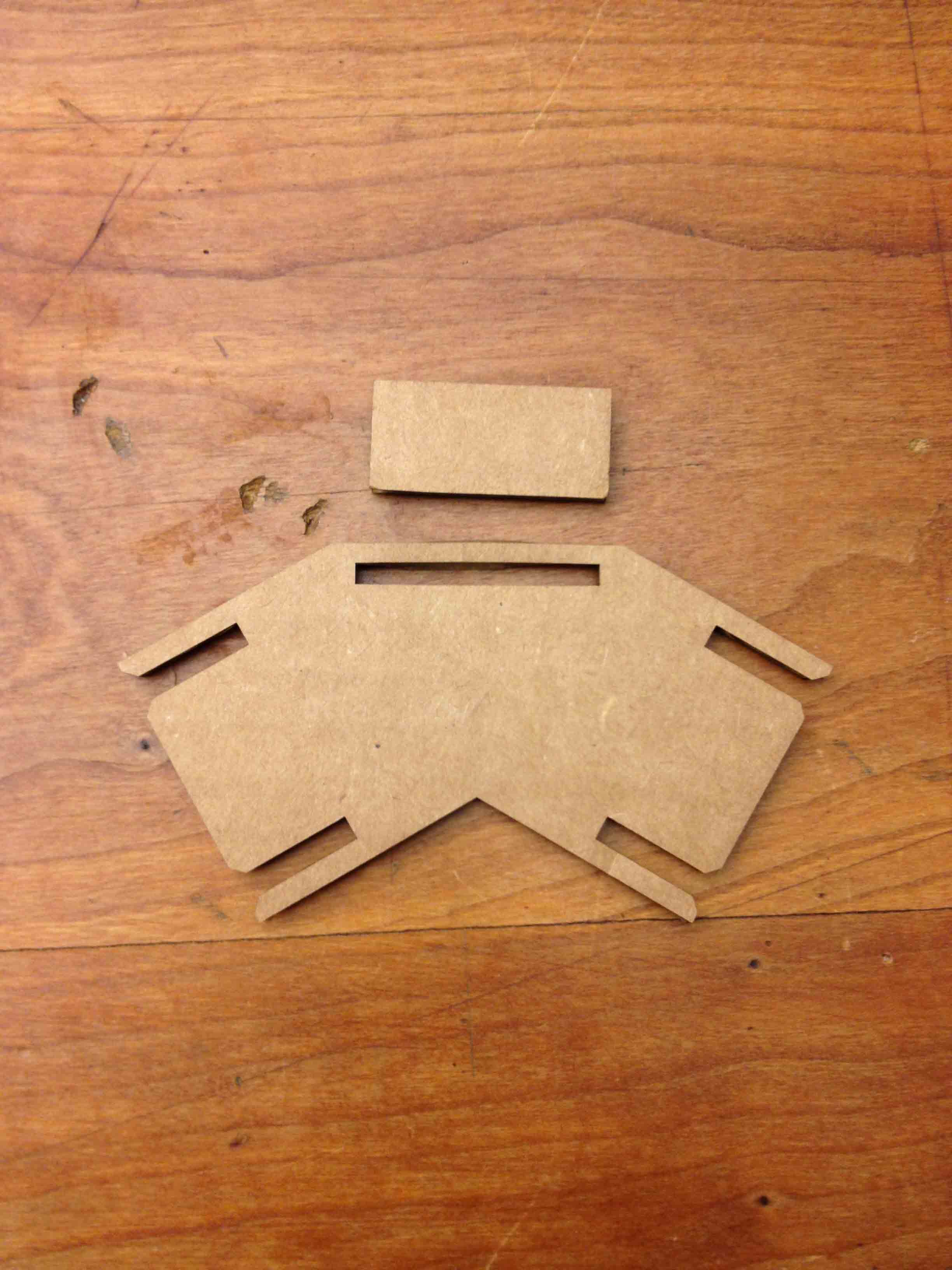
Here is how the flip flop is assembled from its constituent pieces.
The flip flop allowed for surprisingly interesting track configurations. I also quickly realized that it can be thought of as a bit being toggled back and forth in a computer (left = 0 / right = 1), so I used them to build a 4-bit binary counter. It's essentially a smart marble track that counts the number of marbles that have gone down it.
The following video shows the counter counting up to 16. Notice how it resets to 0000 after the 16th marble passes through.
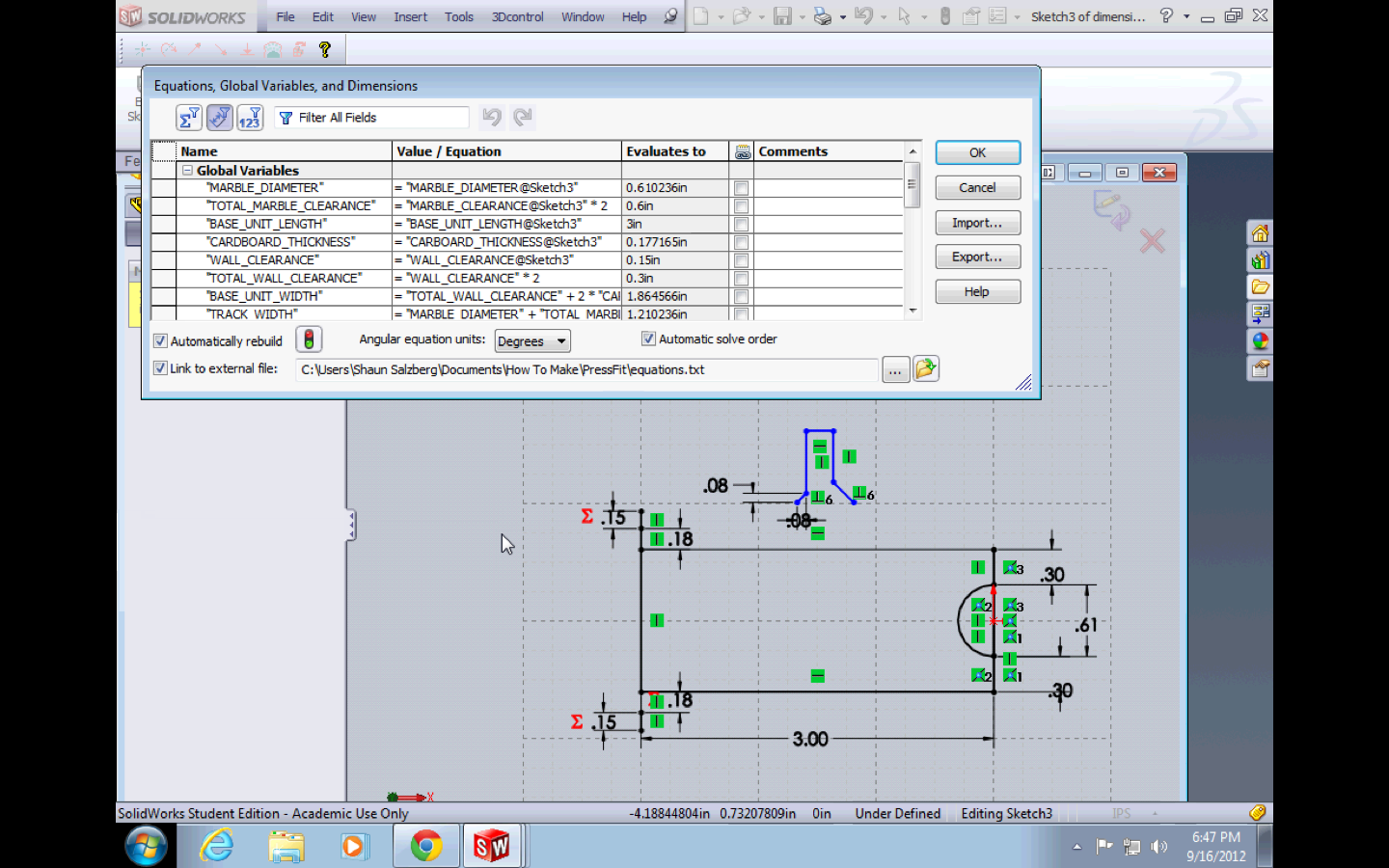
I designed the pieces parametrically using SolidWorks, so that I could quickly and easily change key parameters such as the material thickness or the marble diameter without having to rebuild each piece from scratch. Doing it this way was a huge help, as I constantly had to play around with various parameters to get the pieces to fit snugly, but not too tightly, together. The cardboard is about 4mm thick, and I ended up using 3.5mm spacings to get a nice tight fit.
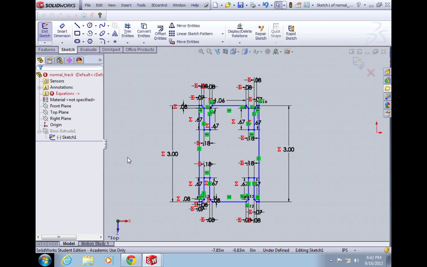
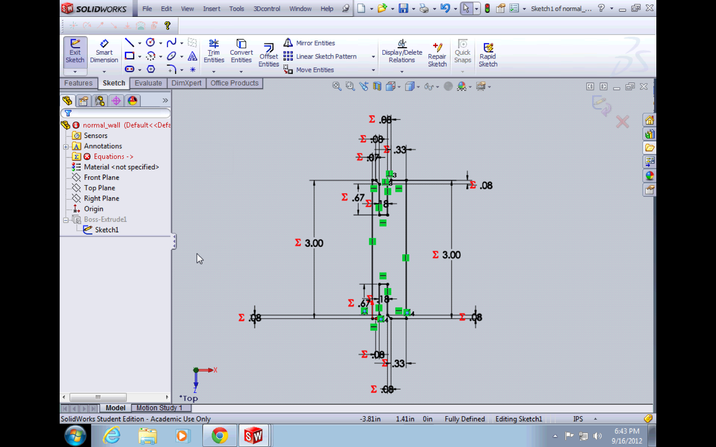
After much frustration, I realized that there actually isn't a standard way of working parametrically in SolidWorks, and there's no great solution for doing it, especially when you want to share parameters across part files. What I ended up doing was creating a part file called "dimensions", drawing random lines in it, and giving them dimensions that are significant to my project (i.e. one line represented the cardboard thickness). I then gave names to these dimensions and referenced them in other part files with a syntax like, "CARDBOARD_THICKNESS@Sketch1@dimensions.sldprt". This is a little verbose though, and it was annoying to write out all the time. So I used the "Equations" feature of SolidWorks to give aliases to these dimensions so I could simply write, "CARDBOARD_THICKNESS@dimensions.sldprt". It was still kind of annoying to work like that though.
I arranged the pieces in CorelDraw, then cut them out on the Epilog laser.
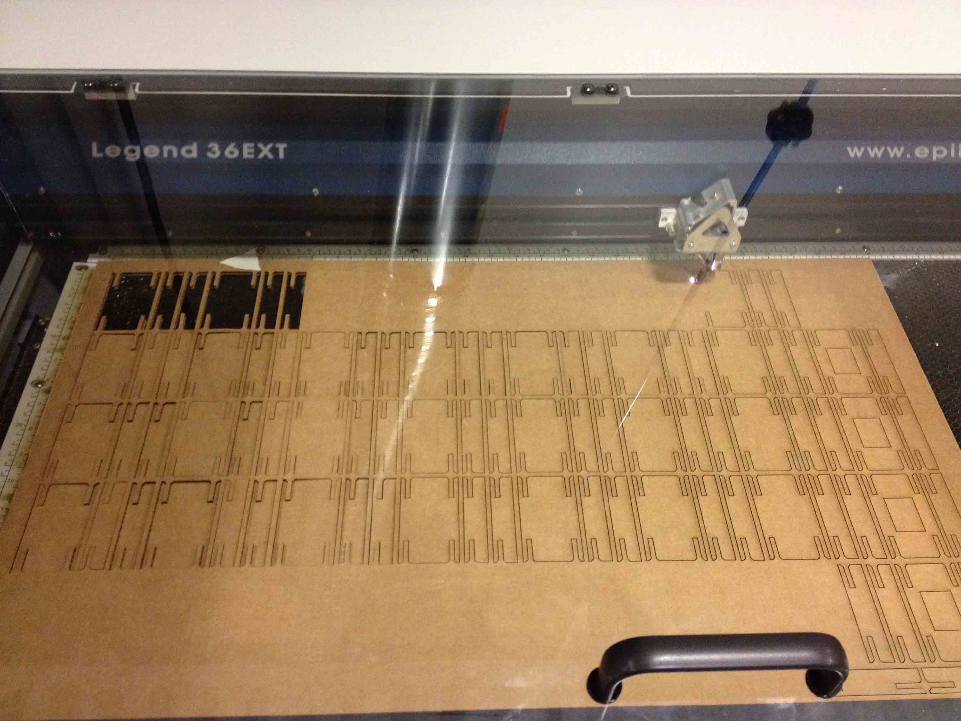
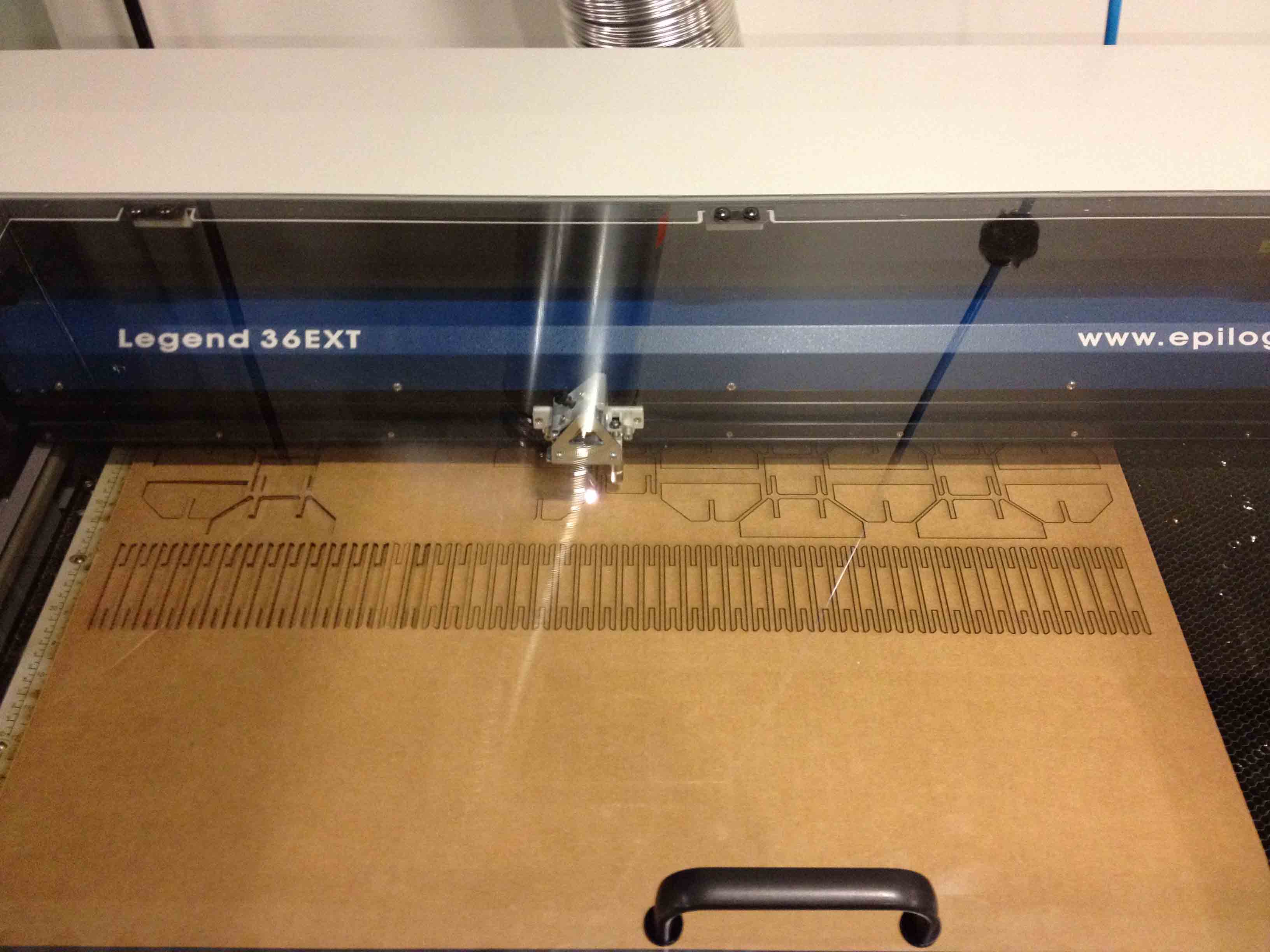
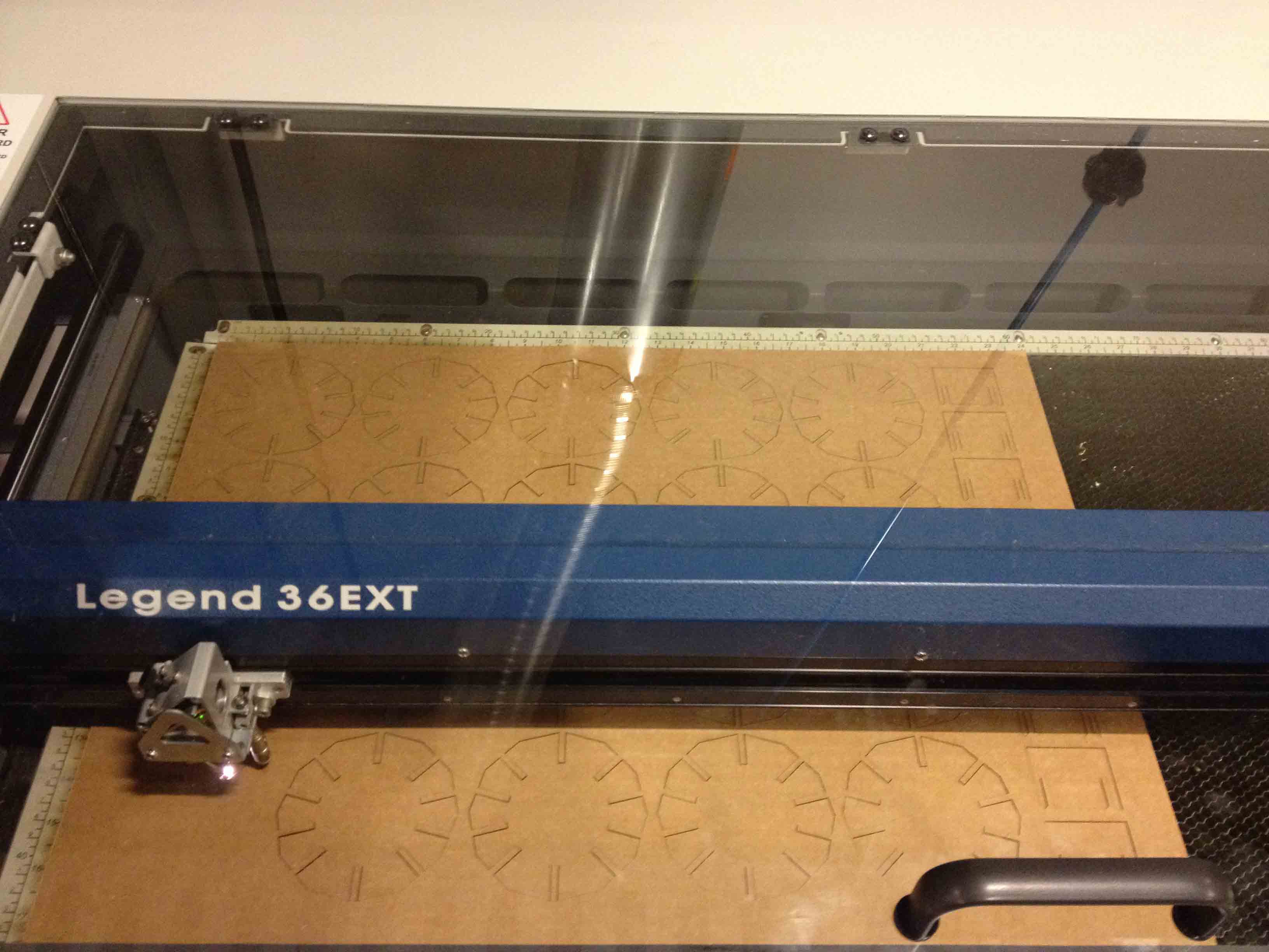
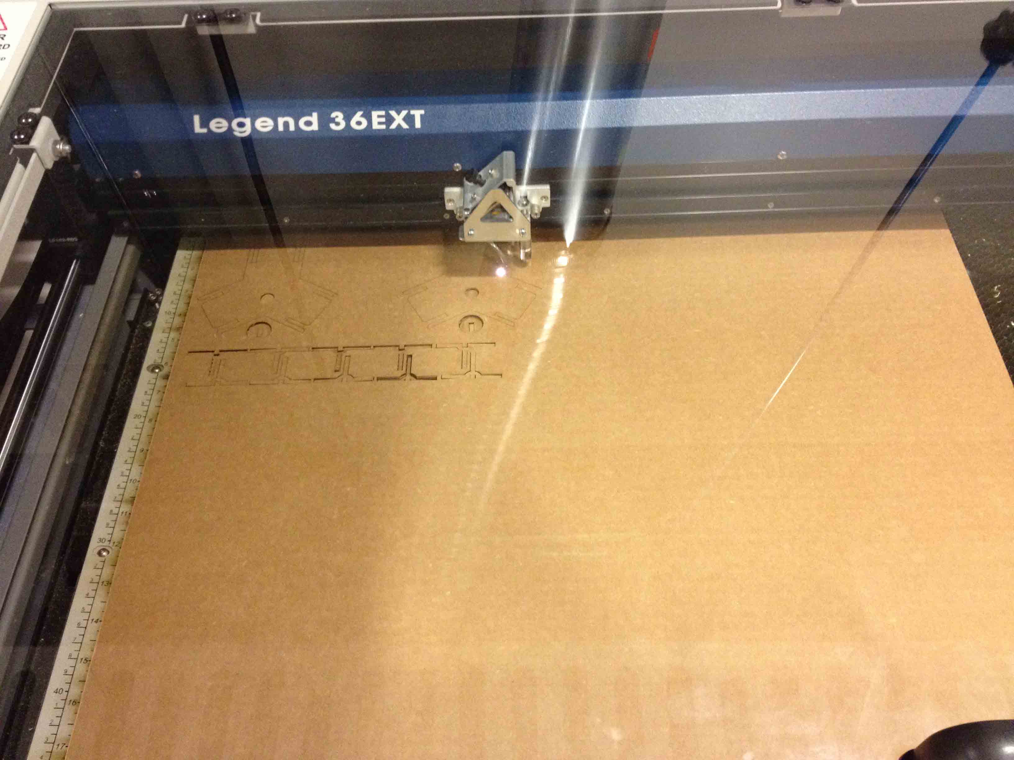
It took a while to figure out the right settings for the laser. When I started out, a lot of the pieces would get stuck to the cardboard since the laser didn't always cut all the way through, requiring me to finish the job with a pen knife. Eventually, I found the perfect settings (50% speed, 30% power, 800Hz), and the pieces slid out like easily without burning.
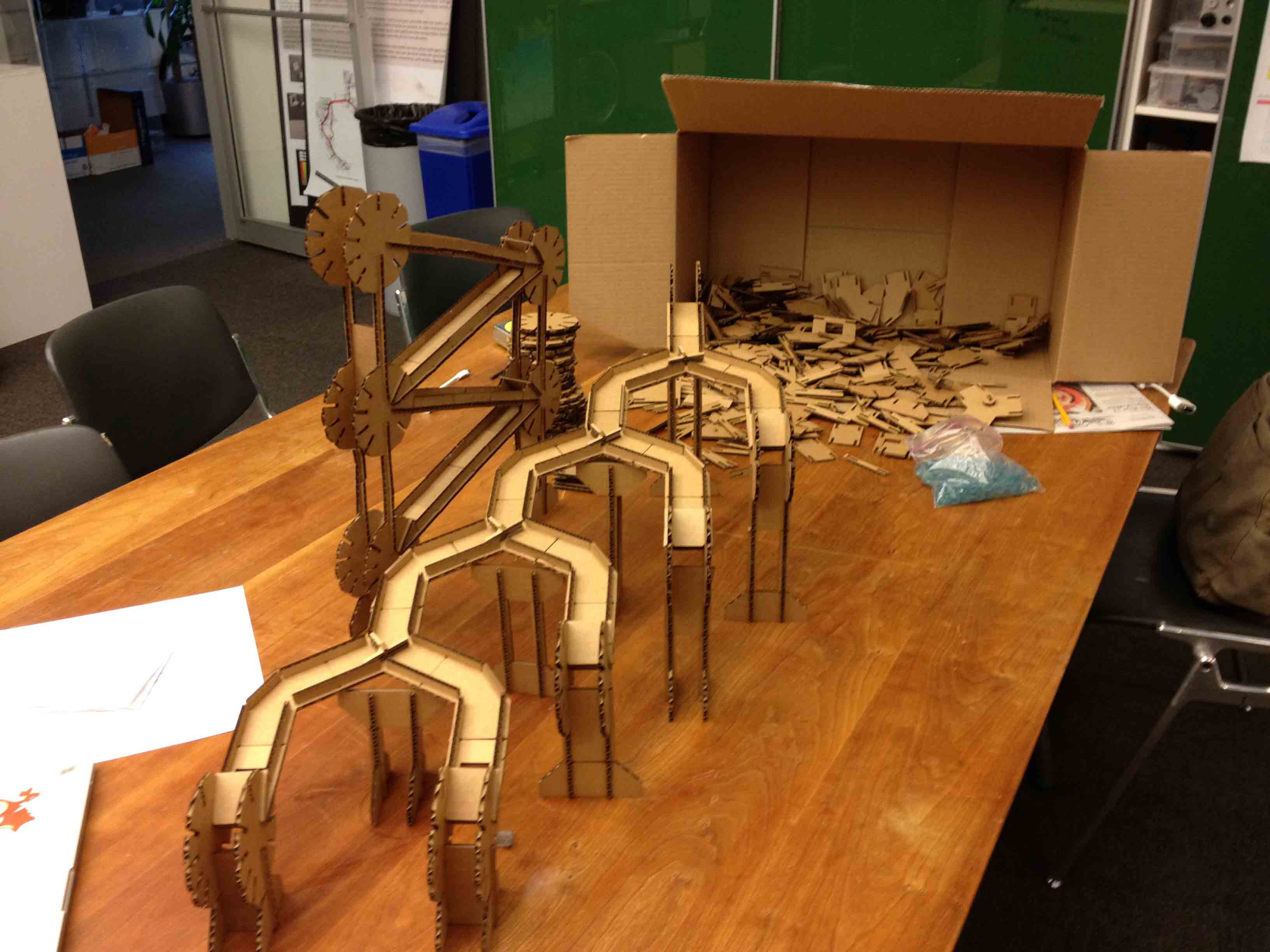
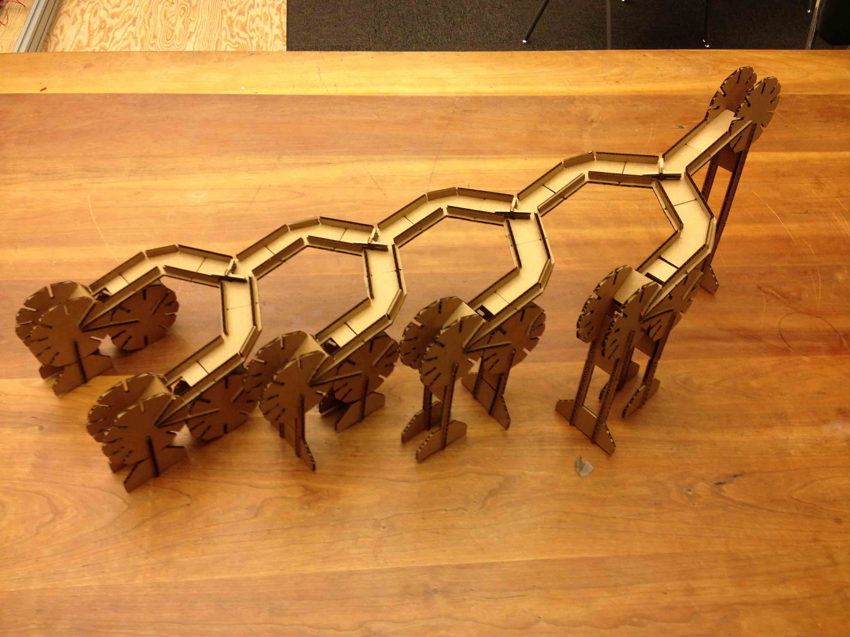
Super excited about my kit, I spent many many hours trying to build a huge, elaborate ball track and was almost done when around midnight, this happened:
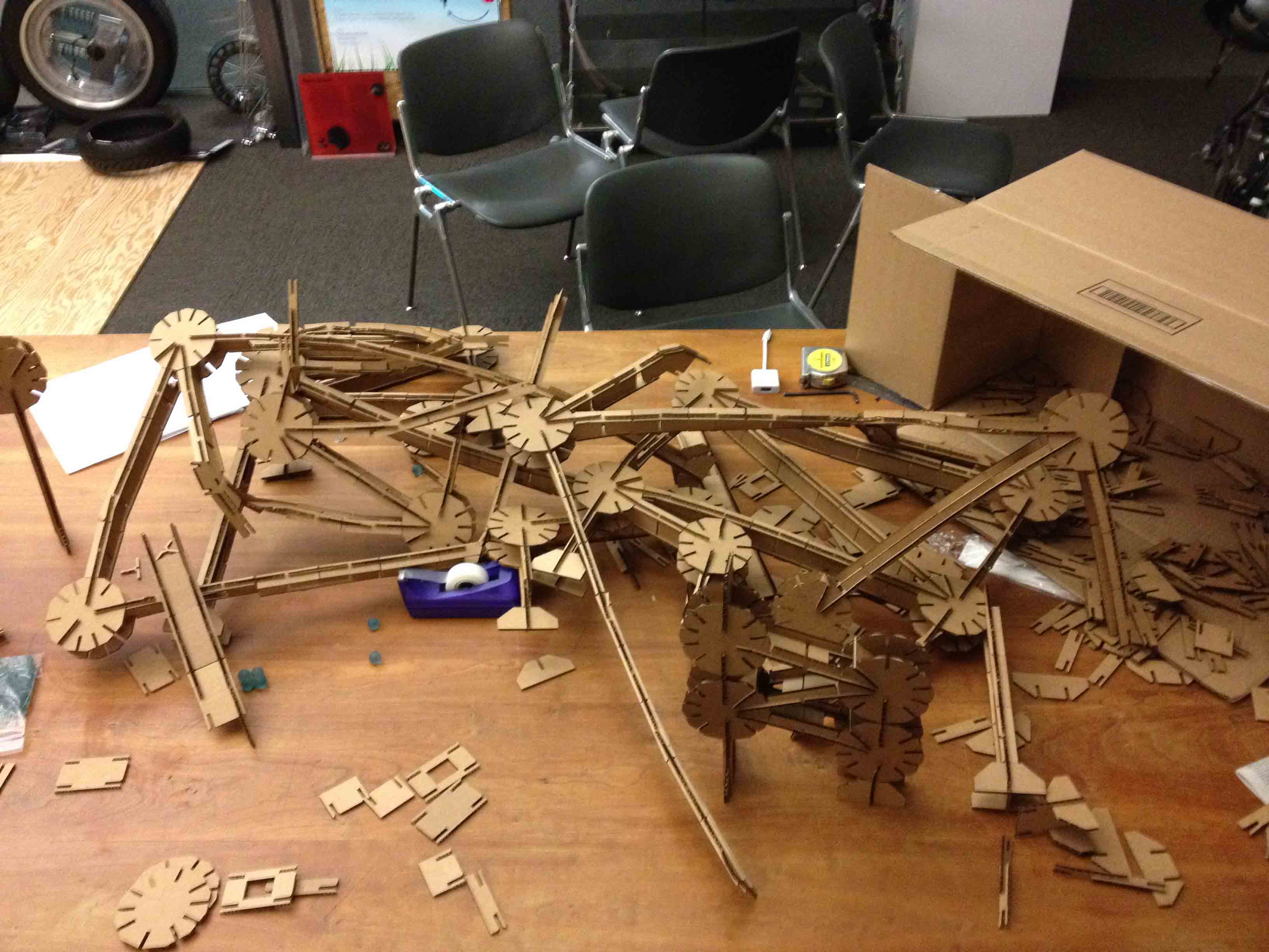
It collapsed under it own weight. Fail. I guess cardboard wasn't designed with structural integrity in mind.
Design Files:
- dimensions.sldprt
- normal_track.sldprt
- normal_track_with_hole.sldprt
- normal_wall.sldprt
- wheel_connector.sldprt
- track_stop.sldprt
- stand.sldprt
- double_stand.sldprt
- stand_connector.sldprt
- flip_flop.sldprt
- flip_flop_wiper.sldprt
- flip_flop_wiper_pin.sldprt
- tracks walls and holes.cdr
- wheels.cdr
- stand_and_stops.cdr
- split_assembly.CDR