
This week we were tasked with designing and printing our own circuit board (with at least a push button and an LED), though I had thought the assignment also involved programming the board, too. I decided to make a little ghost toy that vibrates and flashes its eyes whenever someone knocks into it. Unfortunately I didn't get the motor fully working (more on that later), so now its eyes only flash. Below is a video of the final product. Notice how it activates when I hit the table.
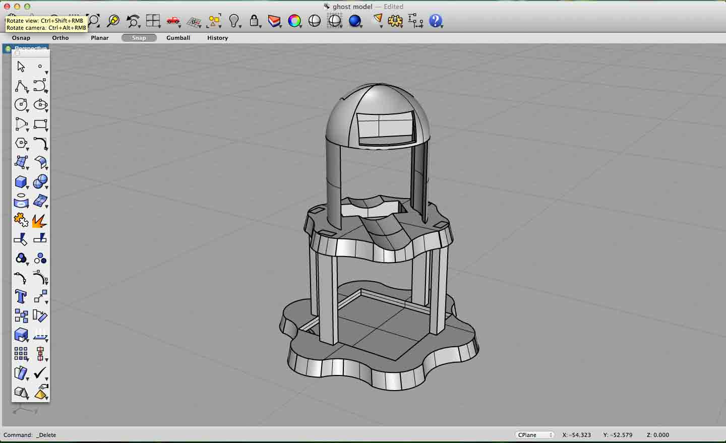
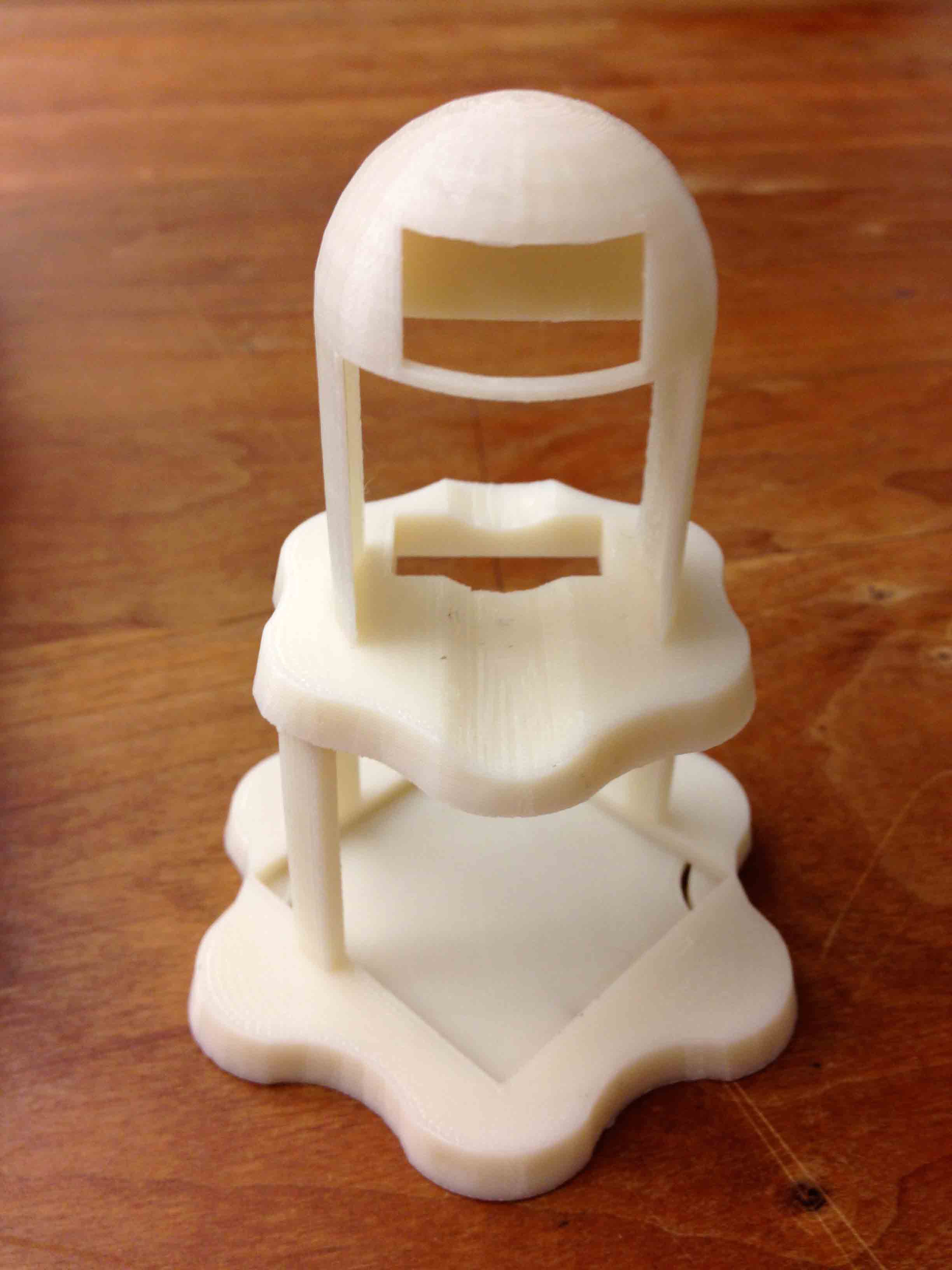
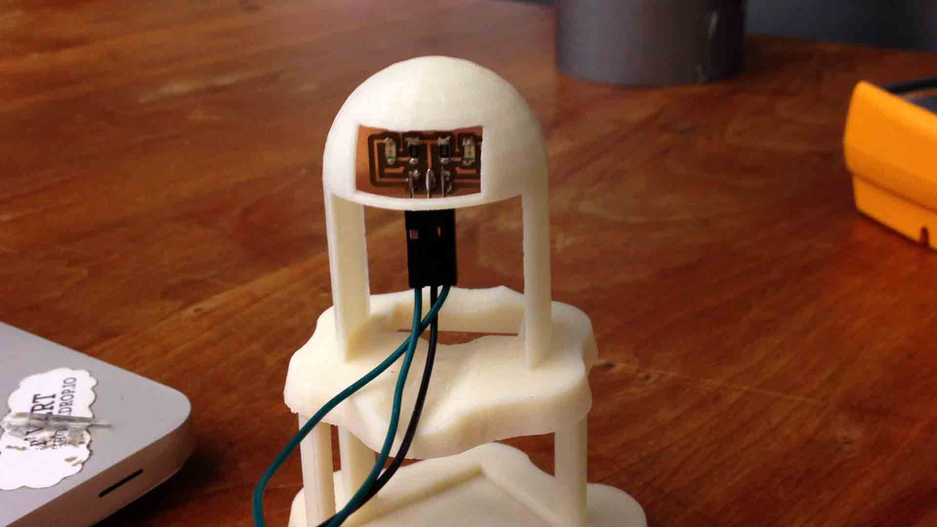
To build the ghost, I first designed and 3D printed the enclosure. The basic skeleton allows a cloth to be draped over it so that it contours to the shape of the ghost, and there are also slots for the eye circuit board, vibrating motor, base circuit board, and battery.
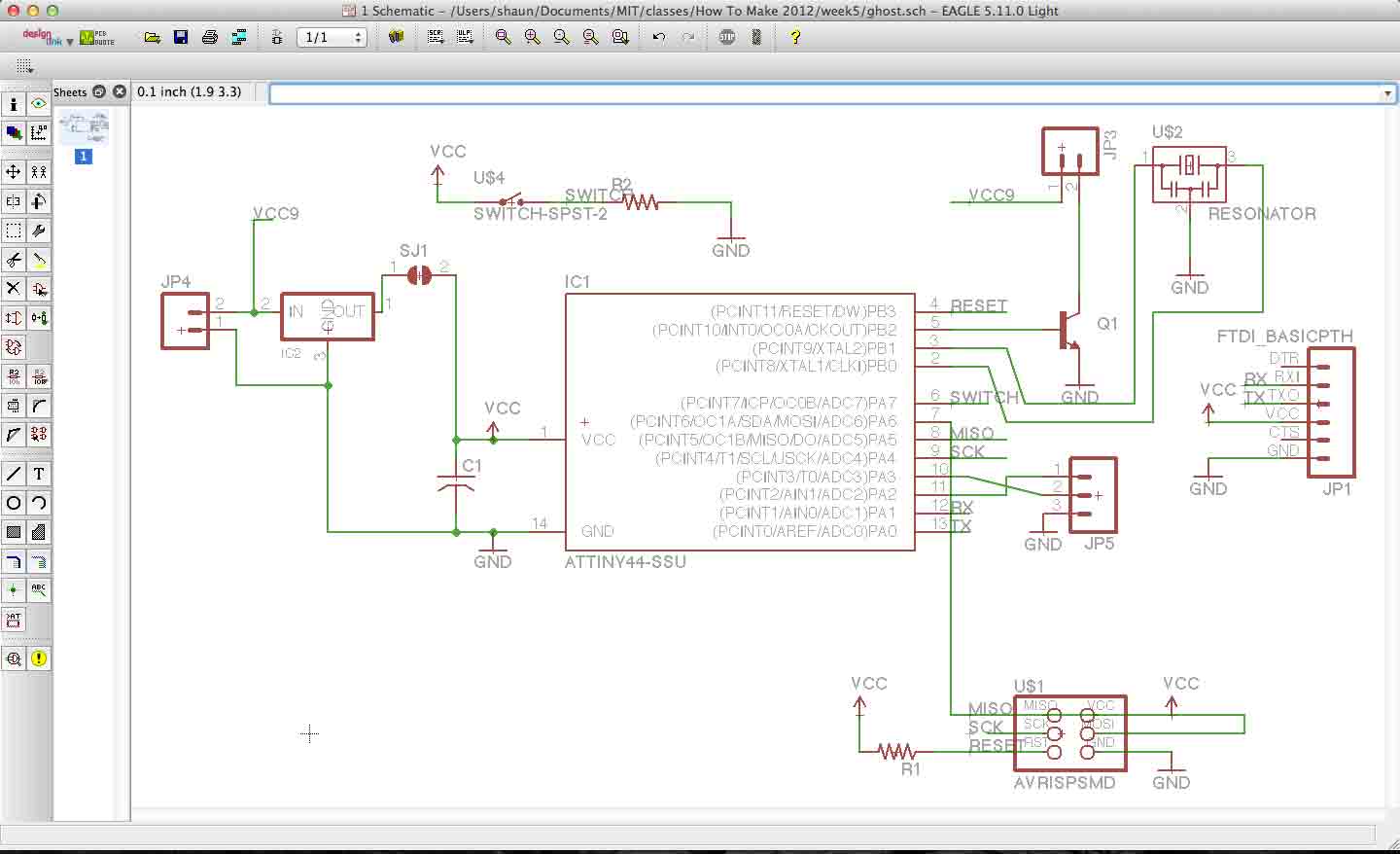
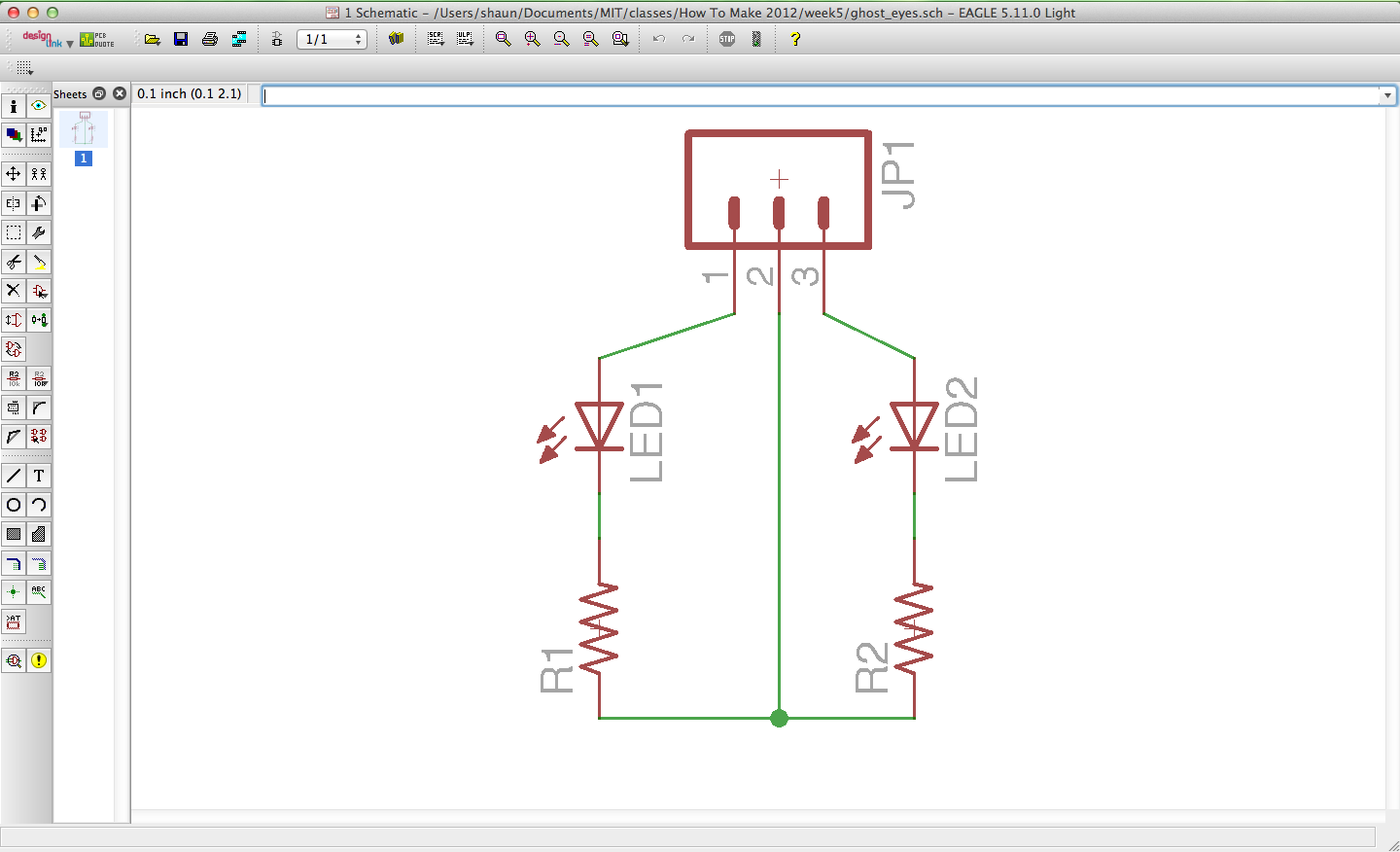
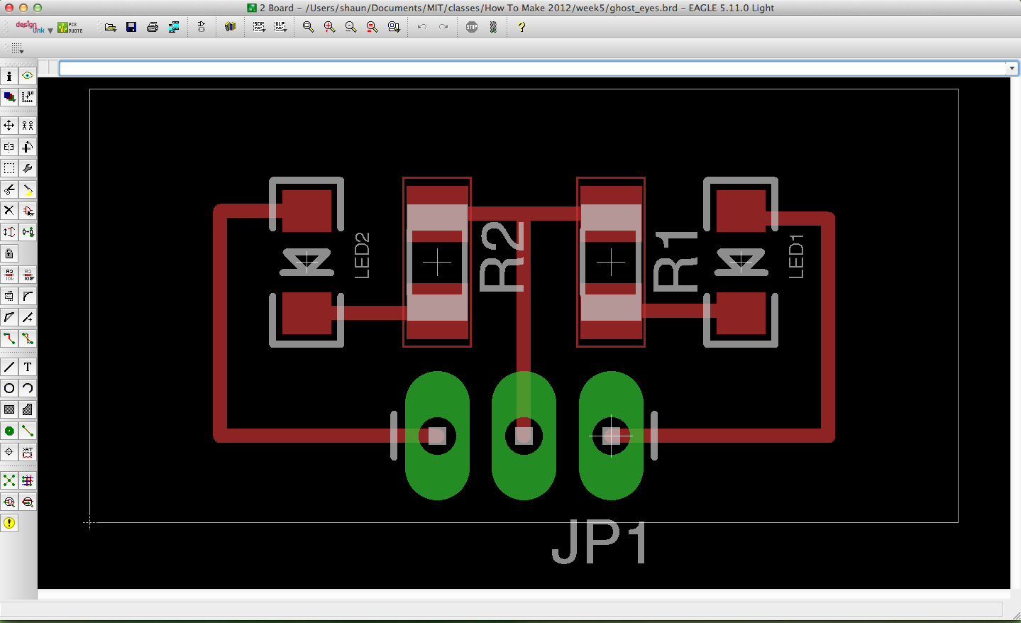
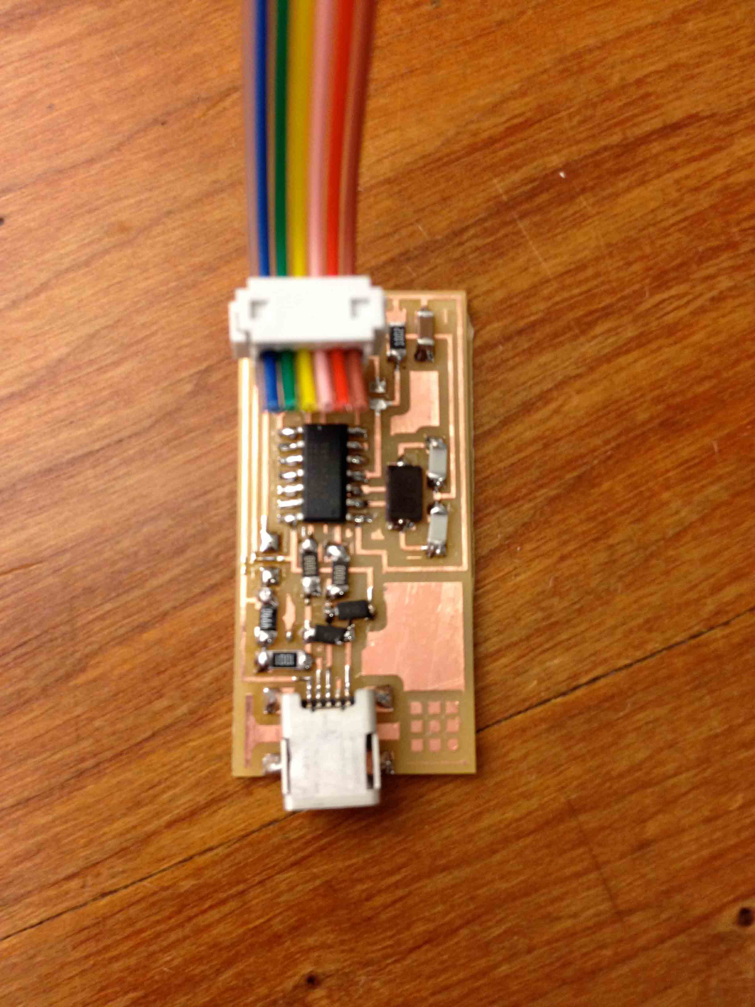
I then designed the basic circuit board with Eagle, which is a slight modification of the one given to us in class. I added headers for a 9V battery to be plugged into, a 5V voltage regulator, and headers for the separate eye circuit board and motor to be plugged into. The 5V supply coming out of the regulator powers the attiny, but I needed the raw 9V to power the motor (the current coming out of the output pin of the attiny was not enough to drive the motor), so I added a transistor to switch the motor on and off based on a signal coming out of the attiny. I also added a tilt switch as the movement sensor. A tilt switch is just a metal ball inside a metal can, which closes two contacts at the bottom of the can when vertically at rest. So when something jostles it, the circuit is open for a split second, making it a super simple momentary vibration sensor.
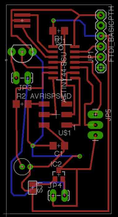
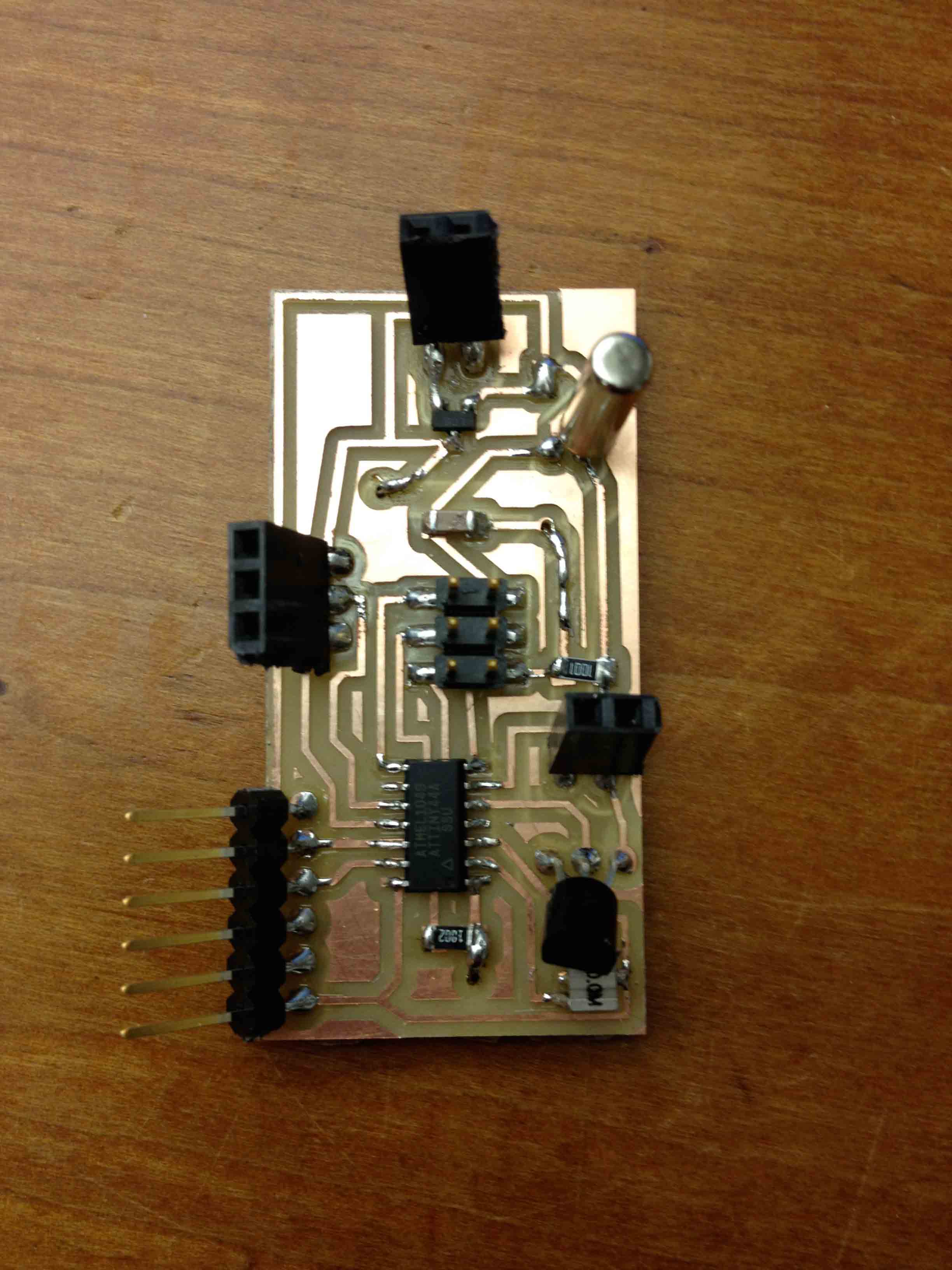
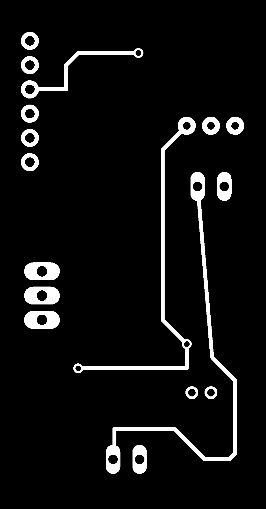
I wasn't able to route all of the traces on one side of the board so I had to make it a two-sided board. The trick to cutting out a two-sided board on the modela is to do it in the following order:
- cut the top traces
- drill the vias and holes
- cut out the board
- remove and flip the board over, positioning in the center of the hole where it was cut out
- cut the bottom traces, remembering to FLIP YOUR IMAGE FILE HORIZONTALLY
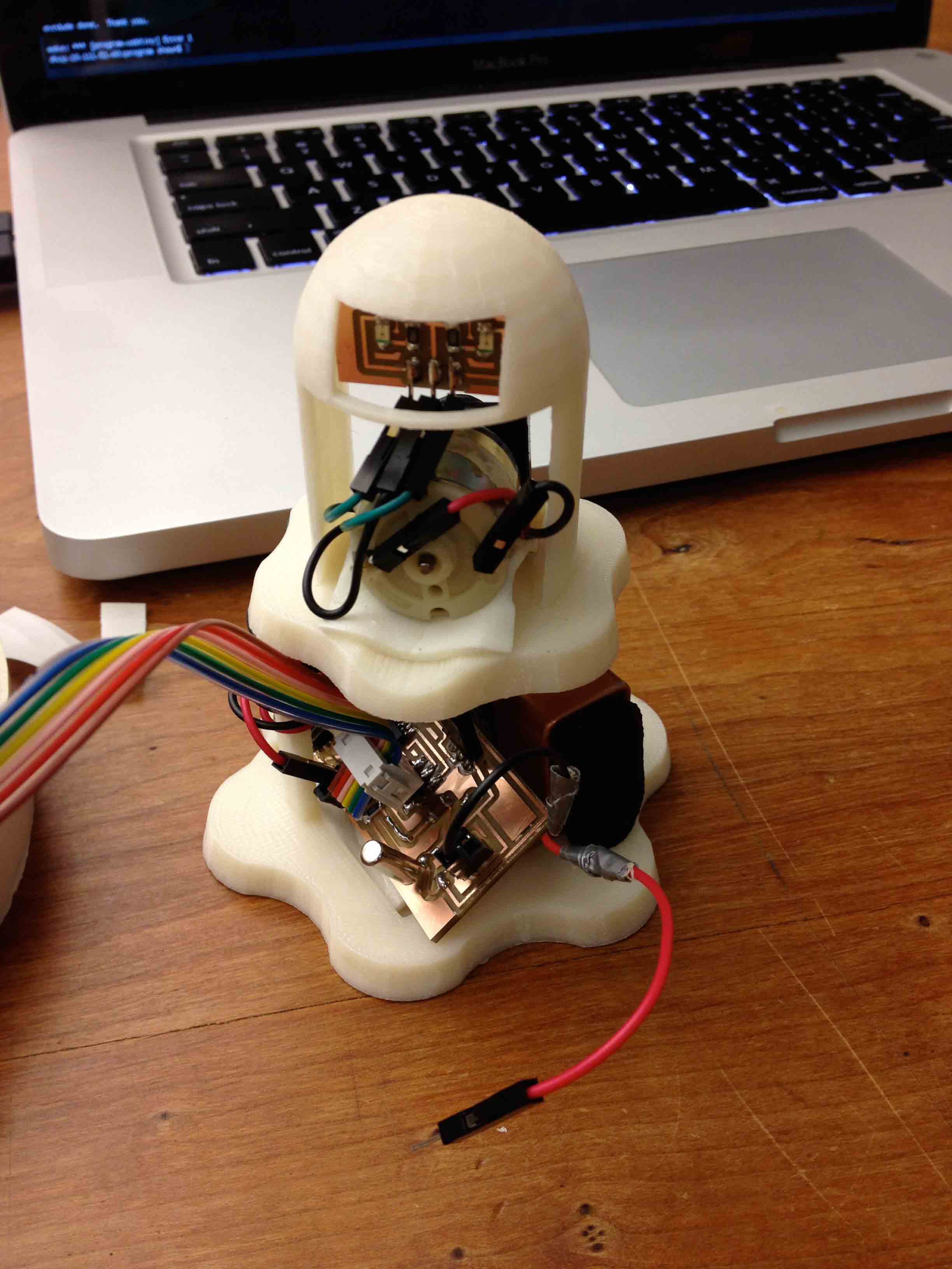
Here is the ghost enclosure with everything inside. I didn't exactly make the slot in the base of the ghost big enough to fit the circuit board and battery together, so they're kind of smushed in there.
I had a lot of trouble downloading code onto this board, which I ended up realizing was just because the FabISP I made previously wasn't working correctly. I had tried to be fancy and made Andy's ISP instead of the standard ISP, but it never worked right for me. So I also spent some time this week remaking my ISP, this time with the standard designs.
I was finally able to get the test code provided to us onto the board, so I then set out to write my own code to control the ghost. It basically says that whenever the tilt switch is open, turn on the motor, blink the eyes for a little bit, then turn off the motor. I also put some pauses in there after it shakes around so that the ball in the tilt switch can settle down before the code checks if the circuit is open again.
I was lucky enough to get this video of the ghost working correctly before the motor became troublesome.
The problem was that every time the motor turned on, it drew so much current that the voltage going into the attiny dropped very low (less than 1 V), resetting the chip. I don't know enough about electronics to fix this, so I just unplugged the motor for now.
Design Files: