

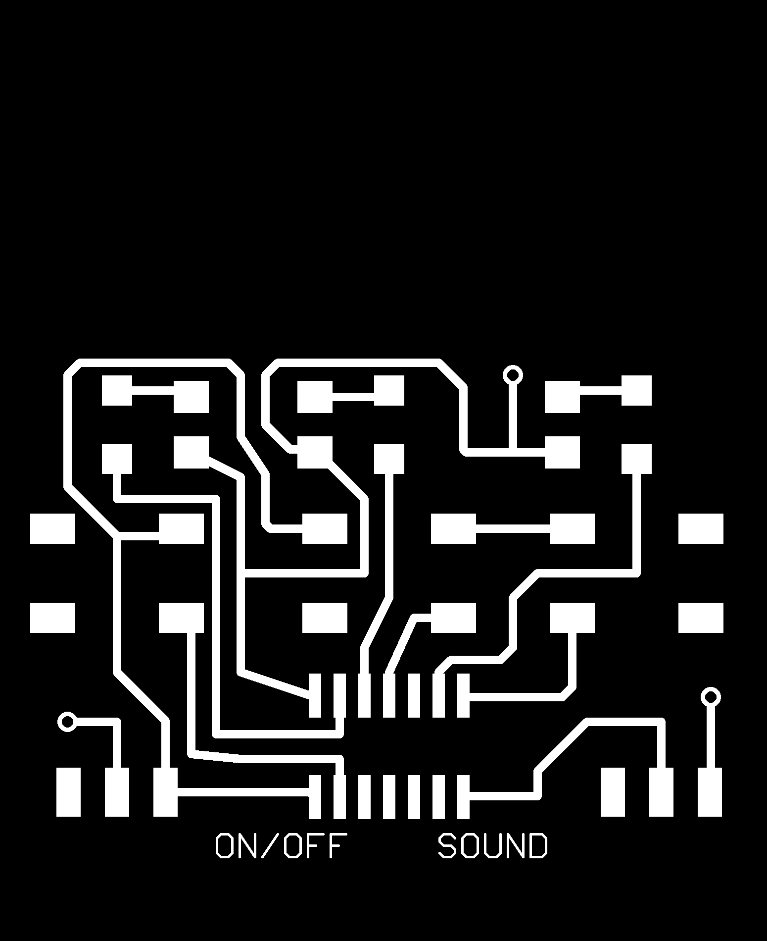
This week we had to read the attiny44 datasheet and write a program to make a circuit board do something. I decided to make a keychain-sized memory game with three LED's and a speaker. The game shows the player a longer and longer pattern of lights (and sounds), and using the push buttons, the player has to repeat it back. Once the player repeats 10 in a row, he wins.
As in past weeks, I designed, milled, and stuffed the board.


There were two minor problems with the board. First, I had decided to cut down on the number of resistors I would need on the board by making use of attiny's internal pull-down resistors on the pins attached to the buttons. However, as I found out after reading the datasheet, the attiny does not have pull-down resistors, only pull-up resistors. So I had to switch the signal going into the buttons from VCC to GND by cutting a key trace with a knife and soldering a jumper going from the button inputs to GND.

The other issue was that I had intended to use a single 3V CR2016 battery to power the board, but as I found out, the speaker requires at least 5V. So I desoldered the CR2016 coin cell holder, soldered on a taller CR2032 holder, and stacked two CR2016 coin cell batteries inside of it to get 6V.
I've been a programmer for quite a while, so writing the program itself wasn't too difficult. I first did it in C, directly manipulating the DDRA/DDRB, PORTA/PORTB, and PINA/PINB registers to set the direction of the pins and to read and write from the pins. The problem was I couldn't get my freakin' FabISP to program the board! I was always able to set the fuses just fine the first time, but after setting the fuses the attiny completely stopped responding and I could no longer program the board OR set the fuses again. I ruined like 4 attiny's that way before giving up and deciding to try use an Arduino as the ISP.


There's a great tutorial from David Mellis on how to use the Arduino as your ISP, and it worked really well for me. I used the clip method instead of the 6 pin header because I wanted to save space on the board. Its a little tough to get it clipped on to the attiny and making good contacts the pins, though. The trick is to get as much solder OFF of the attiny's pins as possible. You can do this by soldering the attiny to board as usual, then using solder wick to get take it all off. There will still be enough solder to hold the chip down, but most of it will be removed and out of the way of the clip. Once the attiny is programmed, you can re-solder it permanently.
Because I used the Arduino in the end, I had to convert my program to Wiring. It was fairly straight forward (replacing the register manipulation with the Arduino's convenient pinMode, digitalRead, and digitalWrite functions). However, I had a small problem with the PA vs PB pins. The Arduino environment seemed to behave correctly with the PA pins, but it did not work for the PB pins. In the end, I had to use the register manipulation method for the PB pins, and the Arduino functions for the PA pins.
Also, in case anyone's interested, last week I did a bunch of low-level hacking as well to make the board super power efficient by putting the attiny to sleep for most of its operation. Here's a reposting of that code. Very useful for things that are intended to be run off of batteries.
Design Files: