networking and communications
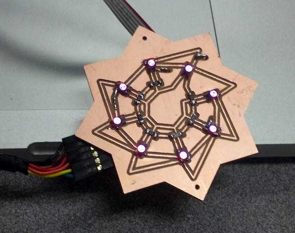
I used this week to work towards my final project, gazebo v2, the portable, drama-enhancing gazebo. For my gazebo, I wanted to create lots of lights which change color to emulate the dramatic sunsets and starry night skies from romance novel covers.
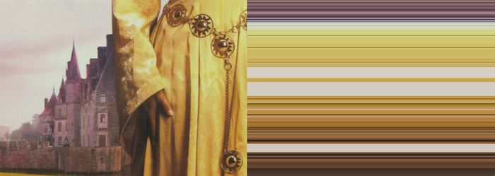
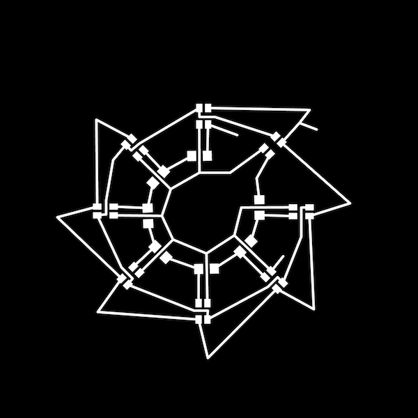
This week I designed my own board, which is a first for me. I was inspired by the ornaments on this woman's dress from a romance novel cover.

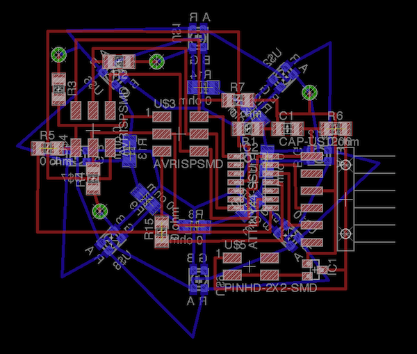
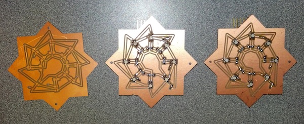
I designed a two-sided board in Eagle, with rgb leds on one side and the rest of the components on the other. I had to fix the rgb led package in Eagle because the one in the fab library is incorrect. There's not a lot of room underneath the rgb leds, so I ended up using a lot of 0 ohm resistors. Make sure the size of your vias matches the diameter of the tool you will be using.
My Eagle file:
I exported the top, bottom, and the vias as three png files and opened them in photoshop. You must make sure the resolution is 2000 dpi in both Eagle and Photoshop, or else fabmodules has problems with calculating the paths correctly. In Photoshop, I did as follows to get the final files to use with fab modules:
1) I copied and pasted all the pngs as different layers in one file.
2) I drew the star cutout over the layers making sure that each layer fits nicely on the final board. Making the star slightly transparent really helps with alignment.
3) I used the "Trim" function, to get rid of all the extra space around the cutout.
4) I then changed the canvas size, adding space equally all around the board (This is to make sure that the layers line up perfectly when you flip the board over. The surrounding area must be exactly equal...one mistake I found out the hard way when milling!).
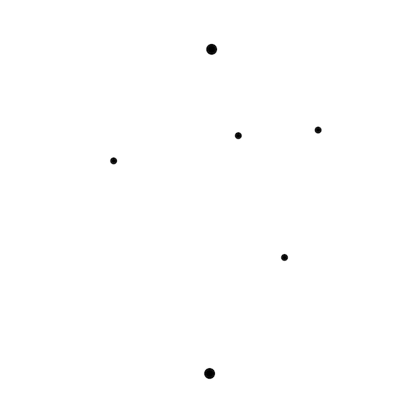
5) I filled the layer with the vias with white to leave only black dots and added black dots where I wanted extra holes in the board for eventually adding string or wire to hang the boards.
6) I added some text to one side of my board.
8) I created a rectangular cutout layer making sure the surrounding space is perfectly equal on all sides.
7) I saved each layer as a png.
8) I flipped all the bottom layers (vias, star cutout, and bottom traces) horizontally and resaved them.
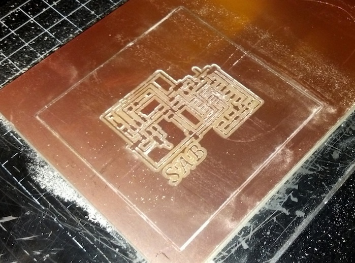
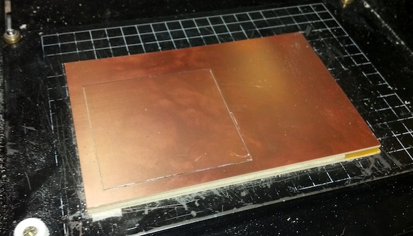
I milled my boards on the Modela from two-sided pcb material as follows:
1) I first milled the top traces
2) I did a rectangular cutout
3) I flipped the board and placed it back in space where I cut it from. Remove tape from one side, put tape on the other side, and make sure the orientation is correct. Tape really well or the board will move around. I used one of the mills to make sure that there was the correct amount of space on all sides of the board (cutting the board out removes material, leaving a gap the size of the mill you used).
4) I milled the bottom traces.
5) I switched to the cutout tool, and I made the vias.
6) I cut out the star shape.

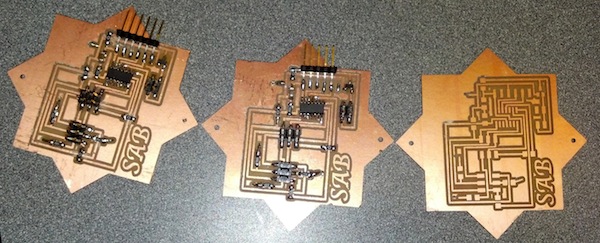
Any traces that didn't cut well enough, I fixed with an xacto. I soldered the bottom side first because the rgb leds are the most difficult.
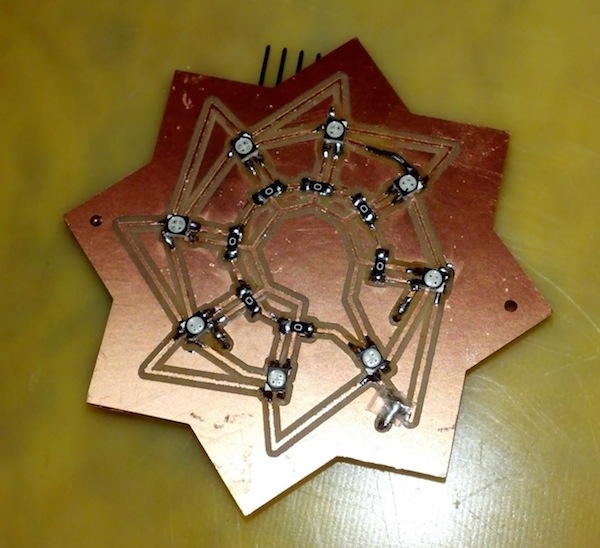
I then did the top components. For the vias, I cut the legs off of a through-hole capacitor. I bent a piece of the wire 90 degrees so it could rest on the trace and soldered it on. This has to be done very carefully because it is easy to lift off your traces. On the other side of the board, carefully bend the wire down while pressing onto ththe connection with something like tweezers so that it doesn't rip off. Trim the wire, and then solder the other connection. It is very, very easy to lift off your traces during this step, which I ended up doing multiple times. I fixed these mistakes with lots of solder and more wire. This was very time-consuming, and I'd like to find an easier way to do this. Overall, this board took many hours to make.
One idea to make the vias easier is to use thin strips of copper tape. I was going to try this on my third board, but I had issues milling the board and the vias ended up not aligning properly with the traces.
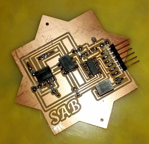
I didn't think through that the FTDI header hangs off the edge of the board. This could be fixed by using right angle headers or maybe bending the pins (but I'm scared to try that considering how long this board took to make!).
I was able to get my first board to program:
I couldn't get my second board to program...I used the multimeter to look for shorts and bad connections but I couldn't find any! I unsuccessfully milled a 3rd board and ran out of time to make this work.
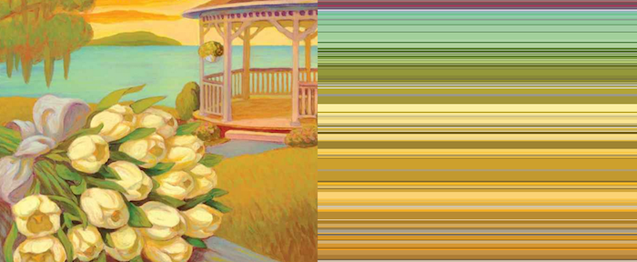
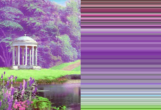
I wrote C++ code (Cinder) to distill images into stripes of color by reducing the number of colors in the image and then sorting the colors. I was going to use this code plus Cinder's Serial library to change the colors of my boards. My goal is to have multiple boards showing different colors from the palettes generated by this code with the colors slowly changing.
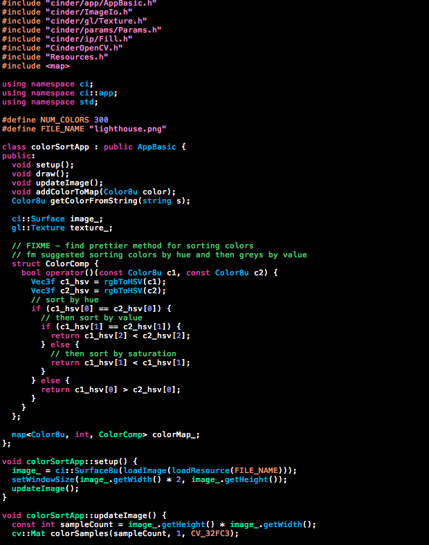
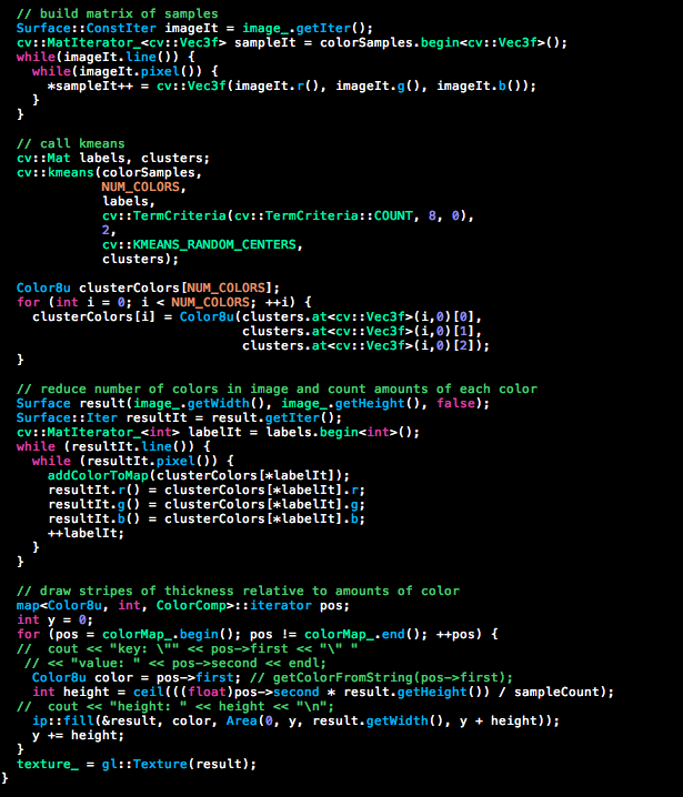
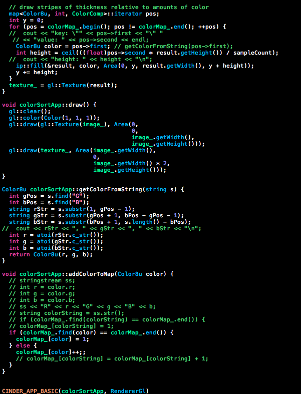
This is the output of my program so far: