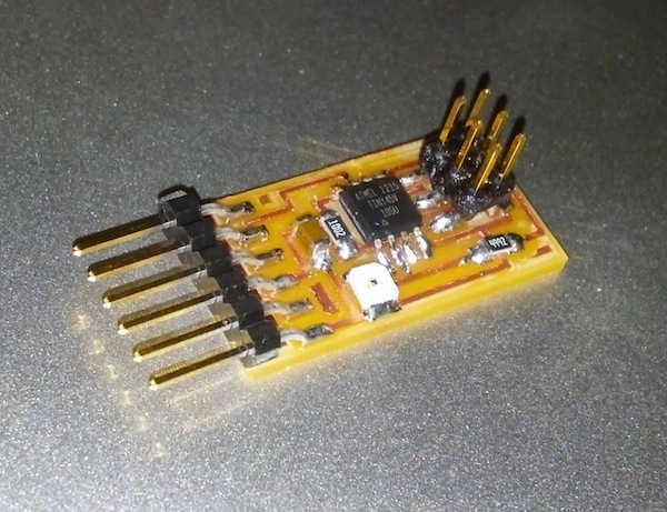
I decided to make the simple example board using a photoresistor this week. I milled the traces png from the class website on the modela. I had a few issues, but nothing new from previous electronics projects. I had to increase the depth a little bit because the surface wasn't completely flat, but no real difficulties .I'm finally getting used to soldering, so that didn't take me much time either.
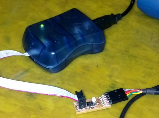
Programming my board is where I started to run into trouble. I decided to use arduino and the avrisp mkII like I did last time. I unfortunately selected the wrong attiny45 from the arduino's "Board" menu (20 mhz clock instead of 8 mhz). When I burned the bootloader with these settings, it said it was successful and everything looked fine. However, I then wasn't able to upload a program or burn the bootloader again (getting an error about bad connections). I then learned that I ruined my attiny45 by choosing the wrong clock speed from the menu. I then used the heat gun to remove it and soldered on a new attiny. With the correct settings, this time it worked.
Another thing I realized was that I needed to install FTDI drivers on my Mac, which can be found here.
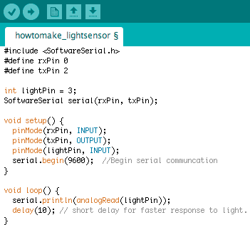
The next challenge was figuring out serial communication in arduino. I looked at the SoftwareSerial examples and combined their code with the simple blink code I wrote last time. The biggest pain was figuring out the pin mappings, which I did by comparing the tutorial from high-low tech with atmel's datasheet.
I printed out the values I got back from the photoresistor, which I could see in the Serial Monitor (small magnifying glass icon in upper right of Arduino IDE).
The numbers get smaller when there is more light and bigger when there is less light. I could have hooked this up to Processing to do a pretty visualization, but I've actually done that before using a light sensor on normal Arduino board so I decided to just leave this as is for now.