2013 How to Make almost Anything
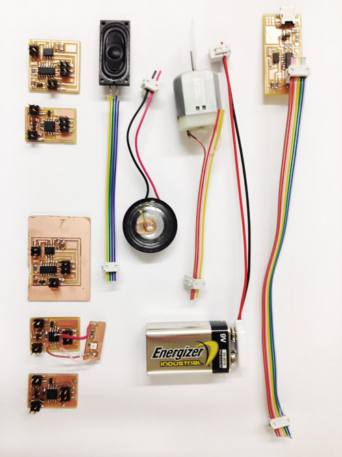
SPEAKER OUTPUT
DC MOTOR OUTPUT
The files i used for the milling and coding of the boards that I made this week can be found here.

In order to attemt to push forward with the coding of the output devices I used the tried and true method of milling and stuffing a board that works. I then would be able to add more components to the existing boards using wires.
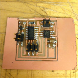
One of the boards did get untaped from the modela and the endmill pushed it around a bit. I was fortunate that the traces were not ruined. I simply cut this one out with a hacksaw.
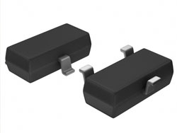
My issues in the beggining centered around this chip right here. I originally thought that the MOSFET and the voltage regulator were the same chip. I also did not realize that there was N and a P type. Not having the right chip results in orange flashes, smoke, broken traces and a ruined board. So it is important that you, recognize the difference and know where to locate them in the inventory.
I originally thought the high level of voltage could be the problem and moved on to the power supply to give a lower amounnt of voltage to the board. This of course was not the answer, but it did allow me to learn how to operate the power supply machine.
I also discovered how versatile 0 ohm resistors are at connecting boken traces. they can even be connected on there sides! I probably wont be trying this again, however.
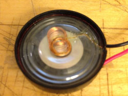
Next on the list is the fragility of the speaker. This was a speaker I purchased but never had the chance to use because I connected it to a board with a short on it, and the speaker became ruined very quickly. It is not necessary to plug in the speaker until you program your board. Actually it is wise to wait because upon reprogramming your speaker can get a quick flash of too much voltage and it could blow it out.
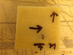
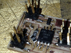
I was having problems remembering the orientation of the different detached components, and even once connected the battery in the wrong orientation adding to the problem of shorting out the board. So I began labelling the back of the board to indicate location of ground and the direction that components face. It has been extremely helpful.
DEBUGGING
This was the first time that my boards were not able to be programmed right away. I learned how to use the mulitmeter and how to read it for measuring the resistance.
First ensure that you are using the right components and they are oriented the right way. The voltage regulators and mosfets are easy to confuse. see above.
The mulitmeter when set to read resistance in ohms, will beep or notify you on the screen when there is not resistance in a connection on your board. The first thing that you want to check is that you have a short. You can do this by connecting the vcc and ground pin of your 2 x 3 header to the multimeter. it should not be zero resistance and therefore should not beep. If it does, begin removing compnents until it does not beep any more. For me the soldering of my components were not the porblem but i had small slivers of copper left behind from the milling. Deburr the board after milling to ensure this doesnt happen. I also wicked away all of the old solder and began replacing the components one by one. I added the microcontroller and then the 2 x 3 header and began checking for a short as a added components on again.
A not on using the heat gun to remove components. Do not place it near plastic pices becasue they will melt before the solder does. Also keep the board elevated only millimeters above the table so you do not risk having another part fall off when the bard comes back onto the table.
After you have ensured that there is not a short it is a good idea to begin checking your trace paths ith the mulimeter to ensure that all the connections are securely fastened. The pin headers seem to be the biggest culprits of unconnected errors and you should use a genorous amount of solder to keep them down.
Moving forward I think that i will opt to always just remove all of my components and then add them back agin if i am having errors. This seems like a quicker method than removing them one by one or remilling a new board.
If your board is still not functioning and your board does not burn when you hook the battery up like mine did, then you can use the multimeter to check for voltage with the battery plugged in. BE CAREFUL becasue with the power in the board touching the wrong pins or connecting two pins together accidentally with the multimeter can short out the board. I did not need to use this so no advice from this point.
FUTURE PLANS
i plan on adding a potentiometer with my dc moter and then gain control through arduino. I need it a variable speed so that i can control the rpm of my music box mechanism. I also need to use a phototransistor as a button of sorts and have my speaker output different tones based ont the intensity of light.