WEEK
10: INPUT DEVICES
Thanks
to Amir and Raj for their help this week
In the embedded programming week I decided I
was going to use the Arduino workflow and code (c +
libraries) for the rest of the semester. I barely have some background in
programming, so the idea for this week was to keep getting comfortable with
this workflow. This probably does not sound so exciting, but this is what I
needed.
Being coherent with the statement above, I
decided to play with three different microcontrollers that I made and try to be
able to program them and communicate with the computer.
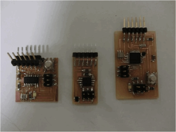
The microcontrollers are (from left to
right):
-
Attiny44
-
Attiny45
-
Atmega328P
Attiny44
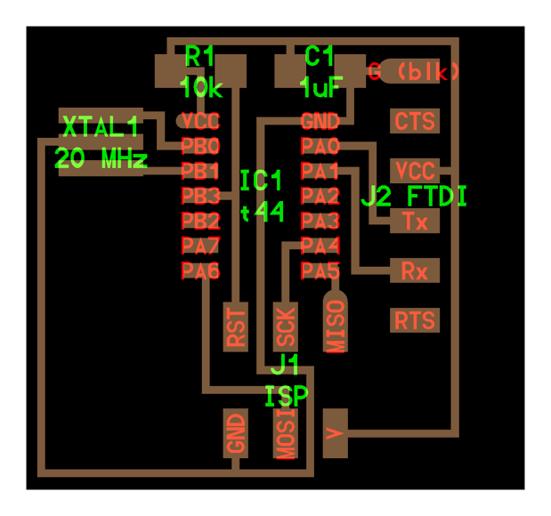
I used the hello.echo
board with the led and switch from week 8. I wanted to get familiar with how
the rx and tx pins work.
Note 1: in order to use the serial with the attiny´s you need to use the software serial library in arduino. I spent quite a bit of time here.
Note 2: you have to pay attention to which
pin is tx and which pin is rx.
The rx
and tx thing made me almost go crazy. I was not
seeing anything through the serial, so I decided to check with the oscilloscope
which pin was really sending information to my computer.
Reading (rx) and
writing (tx) is relative, so this is the logic I found
so far (if you are using arduino code):
- The rx pin in the arduino
program is writing to the board, and the tx is
reading from the board.
- The pin number
for rx in the program refers
to the pin tx in the microcontroller board, and viceversa.
As you can see in the images below, the tx pin in the program is number 1,
which is the rx pin in the board. Another example: as
you will see in the attiny45 board later, if you just want to read, you will
use the rx pin in the board which is the tx pin in the program (just the opposite of what my common
sense tells me)
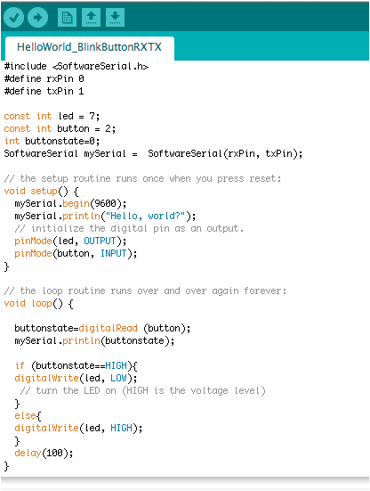
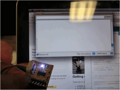
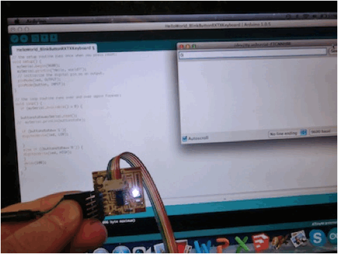
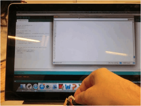
I did two exercises with this board:
1) Reading from
the board: read the state of the switch (0 or 1) from the board (right image)
2) Talking to the
board: control the led through the serial
(left image)
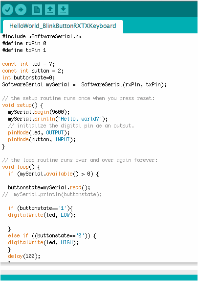
Code for the example in the right:
Attiny45
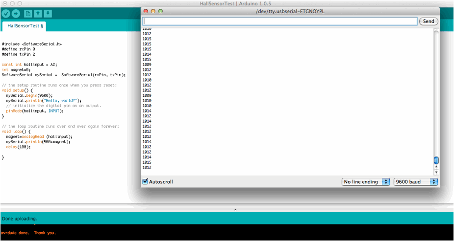
Here I started playing with hall sensors, as
they may be useful for my final project.
Nothing too fancy, but again, the objective
was to learn how to not be scared when programming an electronic circuit.
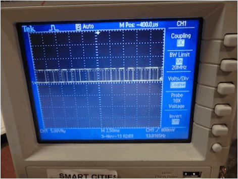
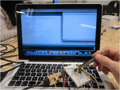
As you can barely see in the image below,
the numbers are changing (you can see how it goes from 4 to 3 numbers) when the
magnet is near the hall sensor.
The code I used. I spent a lot of time to
make it work, as I was using pin 4 instead of pin A2 for the analog input:
Atmega
328P
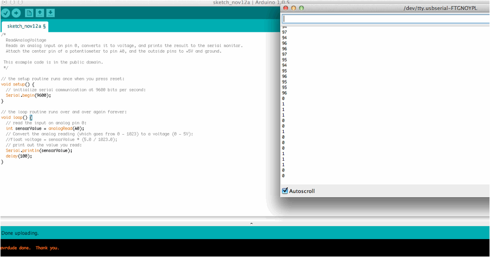
After understanding how the attiny work, now I felt like I was ready to jump to the fabduino. I fabricated the fabduino,
but there were some problems with the board when burning the bootloader. Amir very kindly let me use his fabduino for my tests. In order to burn the bootloader in the fabduino, you
need some files that you can find here http://fab.cba.mit.edu/classes/863.13/people/amir/work/week8.html#1.
Same steps as the attiny´s.
As the fabduino
did not have a connector attached to its analog pins, Amir helped me stick a
connector in the board so that I could use the analog pin. I also used a
breadboard to mount another hall sensor I had.
Note: when uploading programs to the fabduino, you don´t need the fabisp
anymore, but sometimes the upload process gets stuck. When that happened, I
burnt the bootloader again and uploaded again.
I modified one of the examples given by arduino and I was able to read the values. This is when I
realized that this was not really a hall sensor; it was a digital magnetic sensor
(high/low).
Unfortunately, I did not have time to
visualize nicely my results. Taking
into my experience with arduino VS pure c, for the
visualization purpose, I´m thinking about learning Processing before diving
into Python.