WEEK
12: NETWORKING AND COMMUNICATIONS
Answers to my problems from last week:
1- The H bridge not working properly. Charles,
thanks for the answer: “If you look at the A4953 datasheet at
notice how it has undervoltage
protection at 7.9 volts. Meaning if it detects
VBB less than that
voltage, it will not output anything. Because the A4953 is
an automotive grade chip, it makes sense for
it to not totally tank your car
battery if, for instance, it were running something like an
accessory motor.”
2- The servos not
working properly. They were connected to the analog pins and they need to be
connected to the digital pwm pins!
This week I did a few things:
1-
Implement a Bluetooth module for my final project
I was very happy to see how straightforward
this was using the atmega 328p. Using the rx and tx
pins of the fabduino version I did last week, I just
had to connect my laptop to the Bluetooth module and I could easily send
signals through the arduino serial. The program that
controls the dc motor via Bluetooth is the following:
I also downloaded a serial terminal app for
my android phone and was able to control the movement from my phone:
http://www.youtube.com/watch?v=d9duS41gSfA&feature=youtu.be
2-
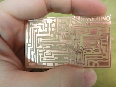
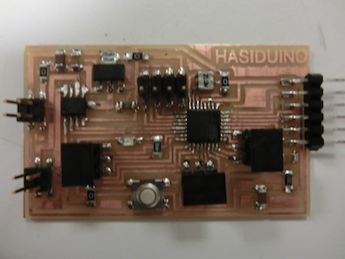
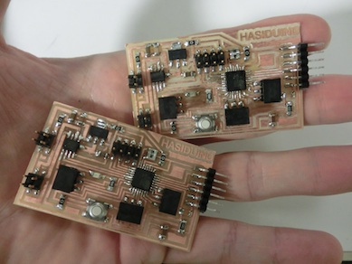
Designing and fabricating a new Hasiduino board
Improvements:
- I created two 3 pin connectors (ground, 5 volt, control signal) that allow
to directly plug the servo in. I did something similar in the older version,
but there I did the mistake of using the analog pins instead of the pwm digital pins.
- I also
connected the h bridge for my dc motor to the pwm
digital pins, in case I need to control not only direction but also speed in
the future.
- It is powered
from a supply using a 5 volt regulator
As you can see in the pictures below, the
design is based on Neil´s fabduino, but I added the h
bridge, dc motor connector, servo connectors, regulator and headers for the
pins. I´m getting decent with eagle and I managed to create a pretty small
board.
Fabricate, burn the bootloader
with the arduino IDE and go!
3-
PLAYING WITH SERIAL BUSES
I was running out of time this week, so I
tried to quickly test an RS232 bus using some existing boards I have.
The idea was to create a network
communicating signals from my laptop to two boards, switching the led of each
board from my laptop and having each board answer to that “led on” request by
saying “Hello, I´m board number X”.
Operating one board work ok, but that´s not
a network yet.
Then, I connected together the rx and tx
pins of the two boards.
Receiving commands worked ok. I could
control the lights of both boards from my laptop. http://www.youtube.com/watch?v=BQvaTi-tPH0&feature=youtu.be
The problem was when making the boards try
to communicate to my computer through the serial. It did not work. Of course,
both boards want to talk to the same bus, and the one that does not talk needs
to be floating so that it does not interfere with the board trying to
communicate. I read in the arduino website that the
way to make a pin float is to define it as an input: PinMode(pin, INPUT). The
issue is that I was not able to use that command to float the tx of the atmega328p. The arduino IDE uses pin 0 and 1 as its default serial
communication, and it does not let me define if they are input or output. I was
not able to make it float.
That´s when I decided to use other pins as a
serial. Remember that in that case you need to use the software serial library
in arduino. Unfortunately, I had issues with the
software serial and I failed to make the boards respond to the call.