Rotem Abeles - How to make (almost) everything – Fall 2013
Week 11 – Output Devices
This week’s assignment was to add an output device to a microcontroller board and program it to do something.
Building on my successful attempt last week at the step response sensor, I wanted to eliminate the need for a laptop (running python) to measure the step response by adding an LCD to my board. This is what I envisioned.
My first step was to make a new board combining elements from the step response board from last week and the LCD example from this week. Luckily, the ATtiny44 had exactly the right number of pins to control both the LCD and the Sensor. In addition, I wanted to replace the FTDI power with a 9V battery. I’ve also added text to help me remember later what should connect where (especially when having 2 2X2 connectors).
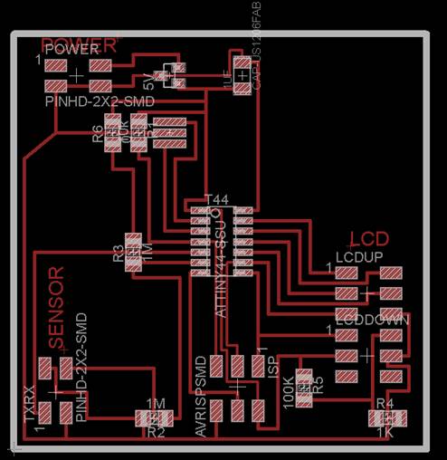

I was glad to see that my proficiency with Eagle improved dramatically over the past few weeks. I couldn’t find a 2x5 SMD part in the eagle libraries so I used 2 2X3 parts to represent the LCD connector.
![]()
![]()
![]()

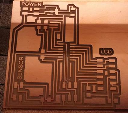
After the milling I noticed that the traces under the microcontroller didn’t come out right, although I ran DRC and didn’t find a problem with my design. Vivek showed me how to re-mill this part of the PNG using a 0.3 width (instead of the default 0.4) in the fabmodules. To fix the traces under the 5V regulator I simply used an x-acto knife.
Soldering went without any problem. I’m getting good at this. Soldering the wires to the LCD was a bit tricky, since the numbers are registered on the back of the board (thus, the numbering order is reverse when you look at it from the top).


Now, getting it to work was again strait forward. I borrowed Mohit’s ISP since I still couldn’t get my win7 laptop to work with the AVRISPmk2. I uploaded Neil’s hello C code and it worked [video].

I found online a cool progress bar code for Arduino. It adds 4 new custom characters (for column width inside an LCD “slot”), thus increasing the resolution from 16 to 80 lines\bars.
//http://www.electronicsblog.net
//Arduino LCD horizontal progress bar
using custom characters
#include <LiquidCrystal.h>
#define lenght 16.0
double percent=100.0;
unsigned char b;
unsigned int
peace;
// custom charaters
LiquidCrystal lcd(12,
11, 5, 4, 3, 2);
byte p1[8] = {
0x10,
0x10,
0x10,
0x10,
0x10,
0x10,
0x10,
0x10};
byte p2[8] = {
0x18,
0x18,
0x18,
0x18,
0x18,
0x18,
0x18,
0x18};
byte p3[8] = {
0x1C,
0x1C,
0x1C,
0x1C,
0x1C,
0x1C,
0x1C,
0x1C};
byte p4[8] = {
0x1E,
0x1E,
0x1E,
0x1E,
0x1E,
0x1E,
0x1E,
0x1E};
byte p5[8] = {
0x1F,
0x1F,
0x1F,
0x1F,
0x1F,
0x1F,
0x1F,
0x1F};
void setup() {
delay(100);
lcd.createChar(0, p1);
lcd.createChar(1, p2);
lcd.createChar(2, p3);
lcd.createChar(3, p4);
lcd.createChar(4, p5);
lcd.begin(16, 2);
}
void loop()
{
lcd.setCursor(0, 0);
//ADC conversion
unsigned
int value = analogRead(0);
percent
= value/1024.0*100.0;
lcd.print(value);
lcd.print(" - ");
lcd.print(percent);
lcd.print(" % ");
lcd.setCursor(0,1);
double
a=lenght/100*percent;
// drawing black
rectangles on LCD
if
(a>=1) {
for
(int i=1;i<a;i++) {
lcd.write(4);
b=i;
}
a=a-b;
}
peace=a*5;
// drawing charater's colums
switch
(peace) {
case
0:
break;
case
1:
lcd.print((char)0);
break;
case
2:
lcd.write(1);
break;
case
3:
lcd.write(2);
break;
case
4:
lcd.write(3);
break;
}
//clearing line
for
(int i =0;i<(lenght-b);i++) {
lcd.print(" ");
}
;
}
Unfortunately, when I tried to test the progress bar code I accidently connected the battery in the opposite polarity, creating a short circuit and killing my board… for my next board I will remember to add a feature to prevent such accidents from happening.