Week 11: Networking and Communications
Introduction
This week we worked on yet another component of electronics, networking and communications. In this case networks could refer to anything involing multiple microprocessors communicating, either wirelessly or wired. Given that my final project is a Bluetooth Boombox, networking and communications is obviously a pertinent topic. Firstly, I will need some experience in wireless in order to get the bluetooth working. Secondly, I intend to make my final project quite modular, using different microcontrollers for different components of the box, so I will need wired communication to manage information between them. I started this week by executing one of the examples as usual, and then went on to attempt to make a prototype of the critical component of my final project (the bluetooth speaker setup). Read on to find out more.
Wired Communication
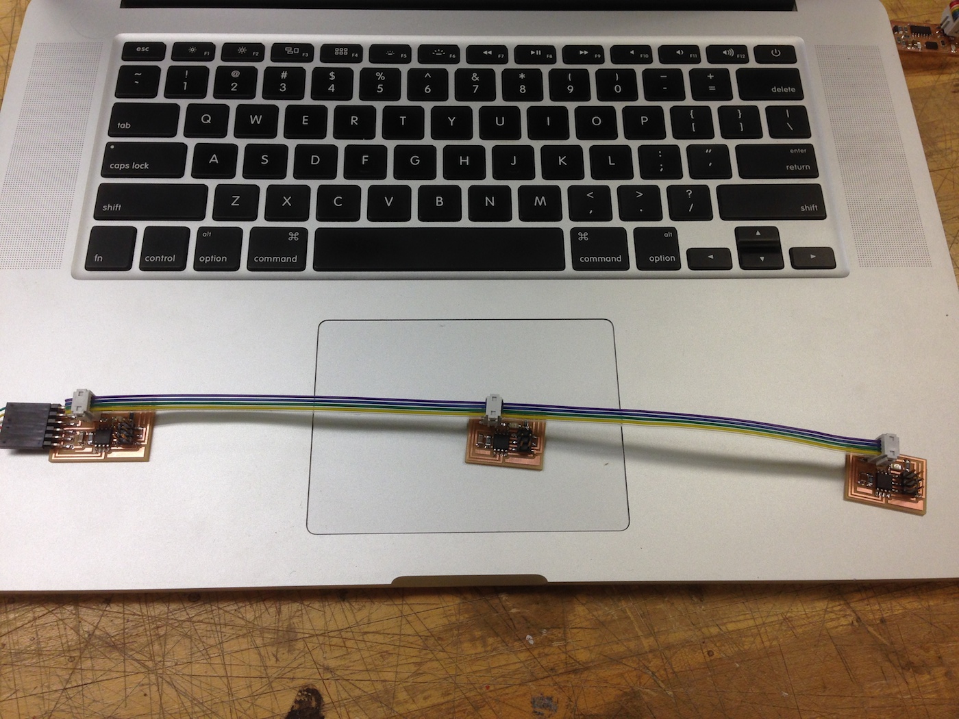
I started by creating the "hello.bus" example presented by Neil in class. In essence the idea is to use a simple UART across the microcontrollers, with a shared RX and TX line. Using unique addressing, the different chips know who is being talked to and how to listen. It went pretty seamlessly, and I didn't expand on the idea at all, focusing more on the next part of the week. Importantly, though, I learned how easy it is to do this and will probably utilize some form of this in my final project to seperate the input (touch sensitive panels) from the output (speaker / bluetooth module) in the final boombox.
If there is one thing I've learned from all of the electronics projects so far (this week included) is that modularity is extremely helpful, and keeping things on seperate microcontrollers might be the best way to continue with that.
Wireless Communication
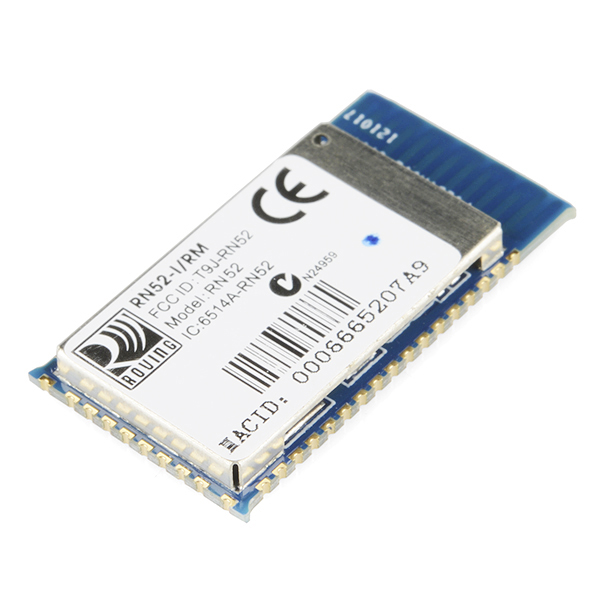
In my final project, I want to use an audio Bluetooth module to stream sound from my iPhone and have basic music controls (play, pause, vol up, etc). The nice thing about Bluetooth is that it has seperated different functions into different protocols, and the protocol for streaming and controlling audio has the lowest learning / implementation curve. I decided a couple weeks ago that I wanted to base my final project on the RN-52 Bluetooth Audio Module which implements these audio protocols. Sparkfun has a nice guide on how to use the module, and it looks like the module does most of the work, so I bought a couple of them to work on.
Design and Fabrication
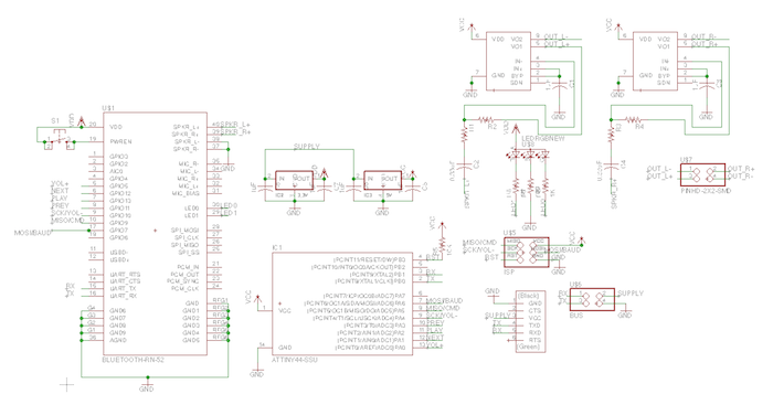
As you'll soon find out, this week was much like last week in that my end product did very little but I learned some incredibly important lessons for the final project to come. Instead of deciding to build the simple circuit presented by Sparkfun in their guide, I decided to add some extra components in the way of a microcontroller to interact with the chip and some amplifiers for the speaker output. Although what I added was relatively harmless in nature (and I had already detected and corrected the problem in my amplifier circuit from last week) the addition of shared communication between the microcontroller, bluetooth module, ftdi, and extra header to connect to another module provided a lot of design complexity.
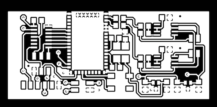
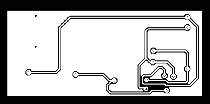
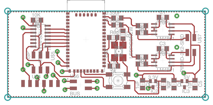
The first piece of this complexity manifested in needing a double sided board. I was reluctant to do a double sided board for time sake but I ended up having to do it in order to accomodate the criss crossing transmission lines. These lines would prove to be a bigger problem later (however) when I realized that the bluetooth module and the FTDI I had operated on different logic levels. The second added complexity came from the radio antenna, which required a ground plane. At first glance this ground plane would seem like a simplification, but that and the double sided nature of the board ended up adding huge complication in the production step because the machine wasn't very cooperative.


You can download all of the files I used to design the board below.
Download Eagle Design Files
When I finally went to produce the board I ran into a plethora of problems. The first was that even though eagle design check assured enough space for the endmill to pass between everything, the fab modules didn't detect this in a lot of cases and left the ground plane connected to traces. This meant having to go over the board and cut a lot of traces. The bigger problem was that the board was just as long as the piece of FR1 I used, so the board slipped loose when milling the bottom traces. This meant the whole bottom side of the board was unusable and I had to manually attach the traces with wires. This turned my hours of board design into further hours of fixing the product. My key takeaway from this is to not push the tolerances of the machine so much so as to allow for a little more error room.
Testing
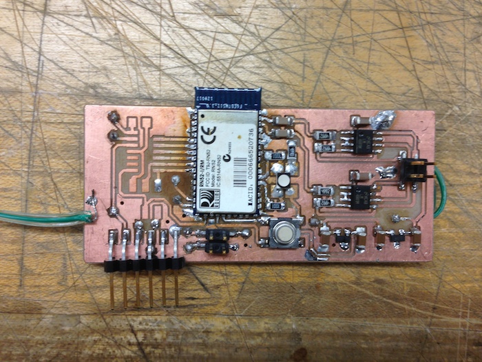
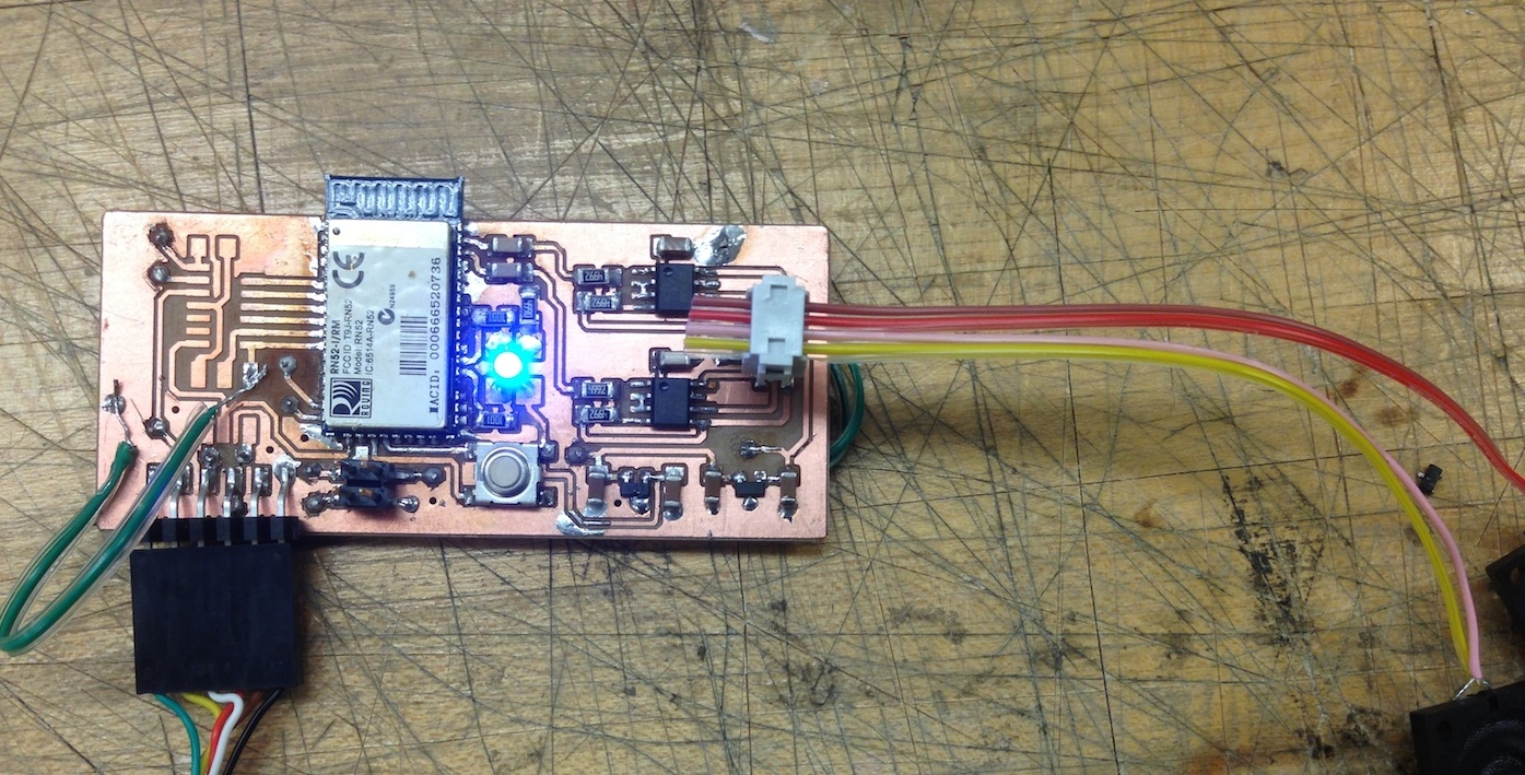
Once the board was produced and stuffed I moved on to actually testing the thing. I stuffed and tested the board in an incremental fashion as I went along, first adding the amplifier circuit. The biggest success this week is that I finally got the amplifier circuit to work excellently, leaving me very confident in that component of the final project.
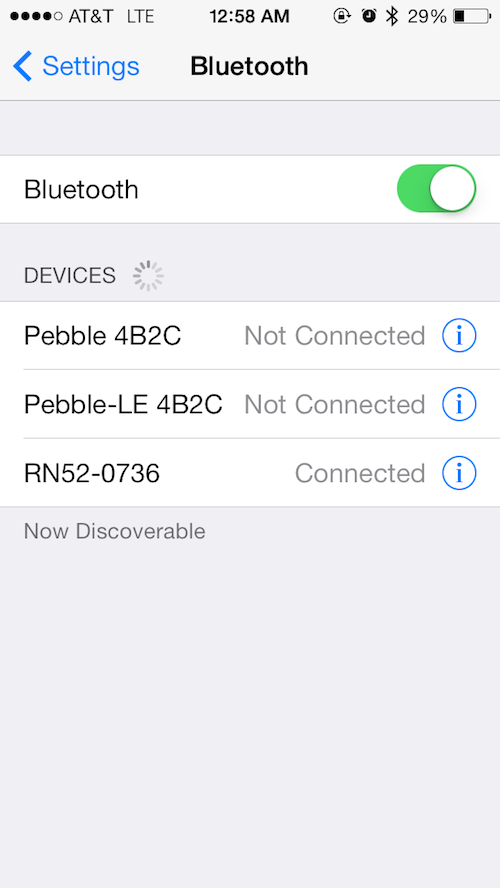
After completing the amplifier I moved on to actually connecting the bluetooth module. I connected it and turned it on, pairing it with my iPhone seamlessly (or so I thought). Unfortunately I kept running into an error where the bluetooth would disconnect after a short period of time or after trying to interact with the iPhone via some command. I couldn't figure out what was going on so I tried a bunch of things. Eventually I figured out that the problem may have been (but I am still not sure) that the command input to the bluetooth module was running from the FTDI cable, which outputs 5V instead of the 3.3V needed for the module. I am not sure if that is actually true because I think FTDI is supposed to output 3.3V but the oscilloscope said differently. In any case, the module became less and less responsive over time eventually becoming all but unusable, leading me to believe that I eventually fried it. The good news is that I have a new module but the bad news is that I have very little idea what the actual problem is and how to fix it. I also don't want to burn out my only other module trying something else that will fail. I think my next plan of attack is to try something much simpler on the module, and gradually add complexity once I know it is stable.
I now basically have 2 weeks to go from where I am now to a working final project, and I haven't even touched design of the box or other hardware (input sensors). I am planning on spending a lot more time on this than I have been so hopefully I can fix whatever problems I've been having with bluetooth relatively quickly. If not I will abandon the bluetooth route and go for a simple headphone connection but that would really take a lot of the novelty out of the project so I am hoping to not have to go that route. Ideally I will know within the next week.