It all started as a dream to create a hoverboard, much like the one from "back to the future", but quickly changed to something more realistic based on the budget I have. The change was not huge, just in dimensions and lift power which led me to create a remote controlled Hovercraft.
Many people have made this before but haven't created almost every single piece themselves. That's what I learned to do.
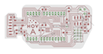
I have designed the hovercraft from scratch using SolidWorks. I cut the design out of foam, wood and aluminium for the structure, motor mount and heat sinks, designed couple of Printed Circuit Boards and customized an existing one that works with radio, created a remote control physical and virtual interface that control and move the hovercraft using radio waves and 3D printed a case for the remote control to give it a better look.
I have learned a lot about numerous fabrication machines, embedded programming, Computer Aided Design and most importantly how to make (almost) anything and cheap. That it of course if you have access to fabrication machinery or enough money to send out the design.
This course has offered me more than I could digest in one semester while doing many other projects simultaneously. That is why i'm sure if I take it again i'll learn a complete new set of skills. This course was a great experience.
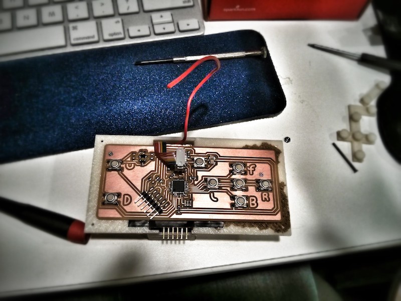
Update from Week 14This week started good, I created another remote control with added voltage regulator to support an external battery and get rid of the computer once and for all.
I did few tests trying to balance the hovercraft. Apparently it's the achilles heel of all hovercrafts. I tried optimizing the skirt's holes but soon realized that the skirt height is not even in the front and back. That's not good news and might result in making a new skirt. This time I will laser cut it to make it perfectly aligned and uniformed.
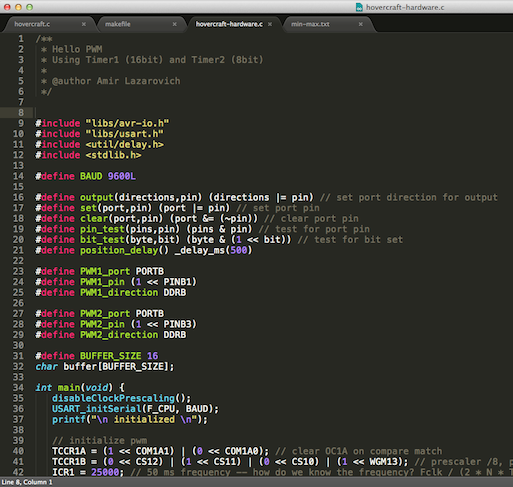
When I wrote the code for the hovercraft I used the Arduino environment. It was easy to start with since it comes with PWM library and few other goodies. The problem was that the SPI library I wrote is unstable there and works perfect when using pure C code. So I started porting my code to C, read about the internal timers of the micro controller and created a simple test code for hardware PWM using Timer1 and Timer2. It took me so much time to get Timer2 to work. When I used an oscilloscope I realized that something is wrong, i'm not getting any signal. It was a stupid typo that got me looking all over the Timer protocol. Well, at least I learned more about the internal timer.
I cut too many holes in the skirt, not so good but still works. After rewriting the motor-control code in C I got better results from the serial port which made the communication more reliable.
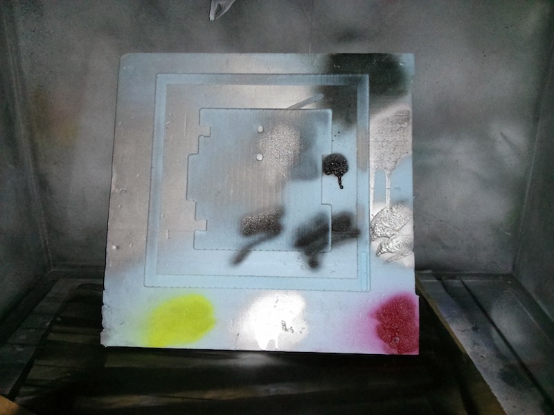
I decided not to paint the hovercraft. Unfortunately all the spray paints I had were either ugly or would dissolve the foam and probably ruin the structure.
Getting good results from the makerbot is not easy. It fails a lot and require a lot time for testing. Depending on the size, every job can take from few hours to many many hours. The remote controller took about 4 hours to finish. The only true good result I got was from the Dimension, a ~$35,000 3D printer. The replicator costs about $2,000.
Here are the parts I didn't make:
Motors & Servo
- NTM Prop Drive 28-26 1350KV / 302W
- Turnigy G10 Brushless Outrunner 1200kv
- Towerpro MG996R 10kg Servo 55g / 10kg / .20sec (I used a similar one)
ESCs
- HobbyKing 30A BlueSeries Brushless Speed Controller
- HobbyKing 50A BlueSeries Brushless Speed Controller
Propellers
- Slow Fly Electric Prop 8038
- Thin Style E-Prop Black 1050
Batteries (choose one)
- ZIPPY Flightmax 2800mAh 4S1P 30C
- ZIPPY Compact 3700mAh 3S 25C Lipo Pack