
The assignment this week was sorta the opposite of last week's: output devices. I wanted to follow through and make the tail-light to my bicycle fender from composites week and thought this would be a pretty opportune time.
Also, after considering my final project and the accidental wide form factor of the lens, it made a lot of sense to turn this into not just a blinking taillight but also as a turn signal. Ideally in the end, it'd be activated automatically by the gps guiding the handlebars and/or if not, directly by the handlebars if you turn.
At first, I'd chosen to use the ATMEGA328P which has teeny-tiny pads but is used in many of the Arduinos and has a good number of pins and power. But because the default footprint left the pads so large, the modela wasn't able to machine them without merging everything together or forcing me to use the .1" endmill.
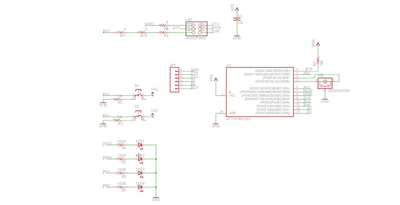
Since neither of those options were ideal and I didn't want to spend the rest of my time troubleshooting, I jumped ship. (I also had a few worrisome vias underneath the chip amongst other issues). I chose the ATTINY44 instead of the 45 to maximize the number of pwm pins and dropped in the led's, two push buttons for switching modes, and a resonator.
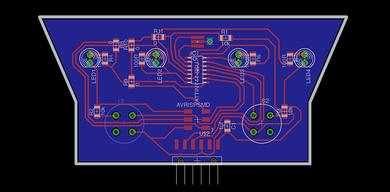
Routing was a pain since I had these large through-hole parts along with a very specific board size to fit the lens. I eventually had to just add an extra rectangular inch at the bottom to fit the button and ftdi output comfortably.
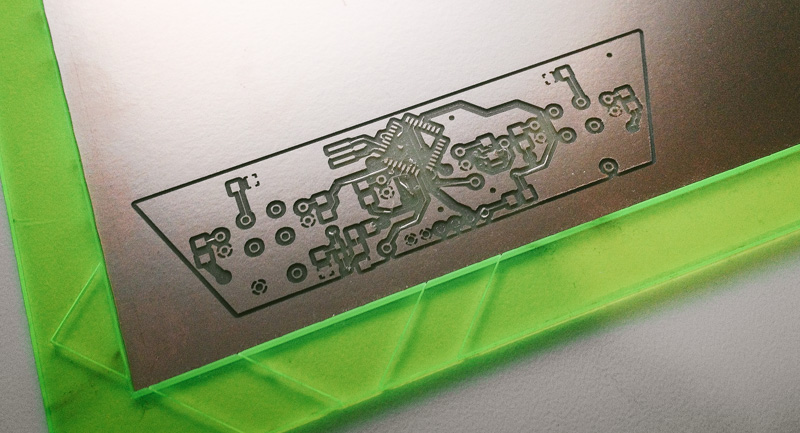
I decided to mill at -1 offsets this week since everyone else had done it and it looked pretty. It took over two hours but after it was done, the results were stunning and clean.
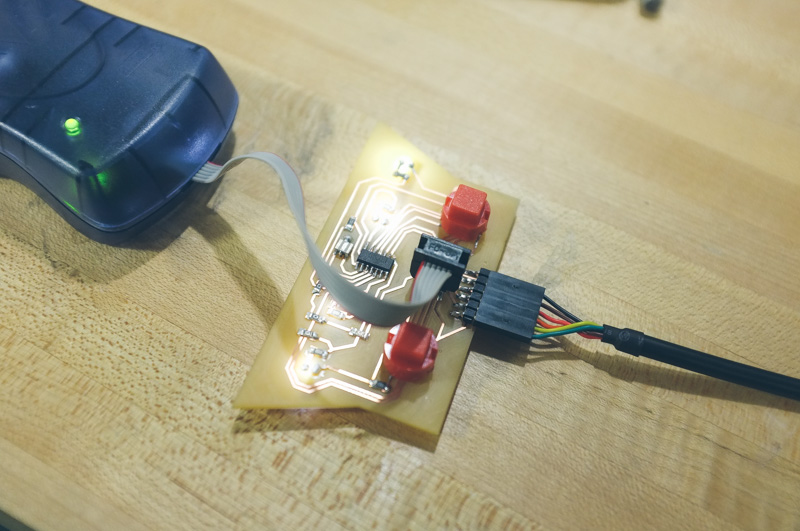
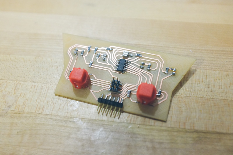
I then hooked everything up and programmed the board with a simple arduino sketch to light cascading patterns depending on which button was pressed.