How to make Almost Anything
Week 10: Output Device - Step response humidity sensor -> RGB LED
0. I plan to design a board connecting step response humidity sensor to a RGB LED, as first attempt to final project (alarm to watering the moss)
1. Schematic
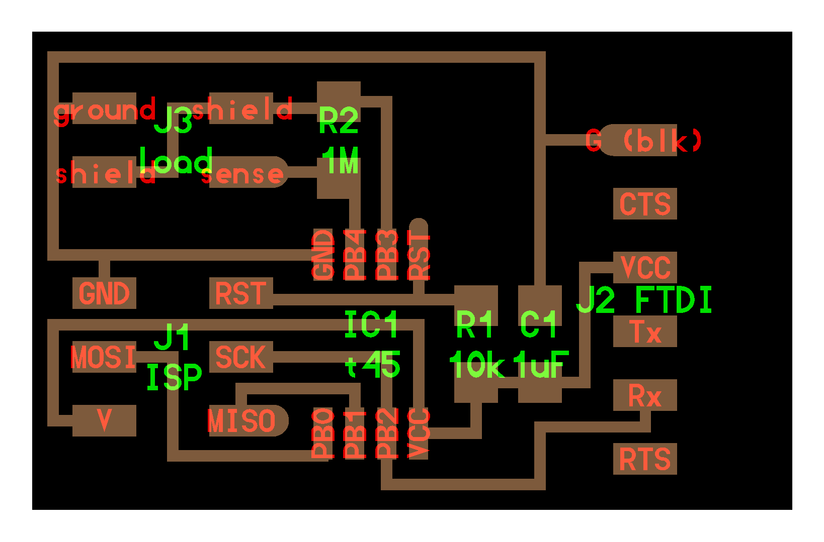
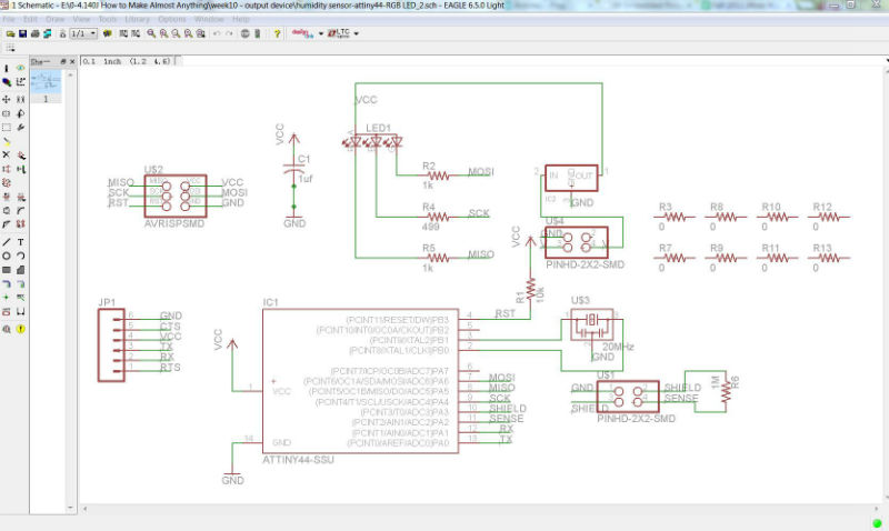
After checking 3 sample board (echo hello-world)(step response board)(RGB LED board), I tried to combine the three, using ATtiny 44 micro-constroller, 2x2 header as sensor connection, RGB LED as output. Schematic design shows below.
NOTES: 20MHz resonator should connect to pin PB1 & PB0 (XTLA presents "clock"); 2x2 header for exterior Battery should mark with different "V", not mixed up with other "VCC"; 0 resistor as bridging should add to Schematic first, then will show up in Board interface
Problem found later: there are 2 possible power resources on this board, 1st is 2x2 header + 5v regulator, 2nd is the FTDI header to computer.
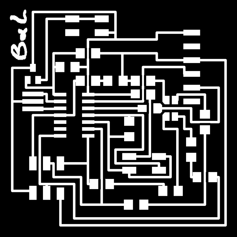
2. Board
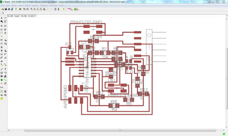
It took me hours try layout out the board to avoid crossing circuit... turns out still need 8 jumpers.
HUGE MISTAKE (discovered after finish the board though)!!!! after add on resistors, should remove the line in-between!!!!!
export PNG and edit in photoshop. Milled the wrong board via Modela, 1/64 for interior, 1/32 for exterior.
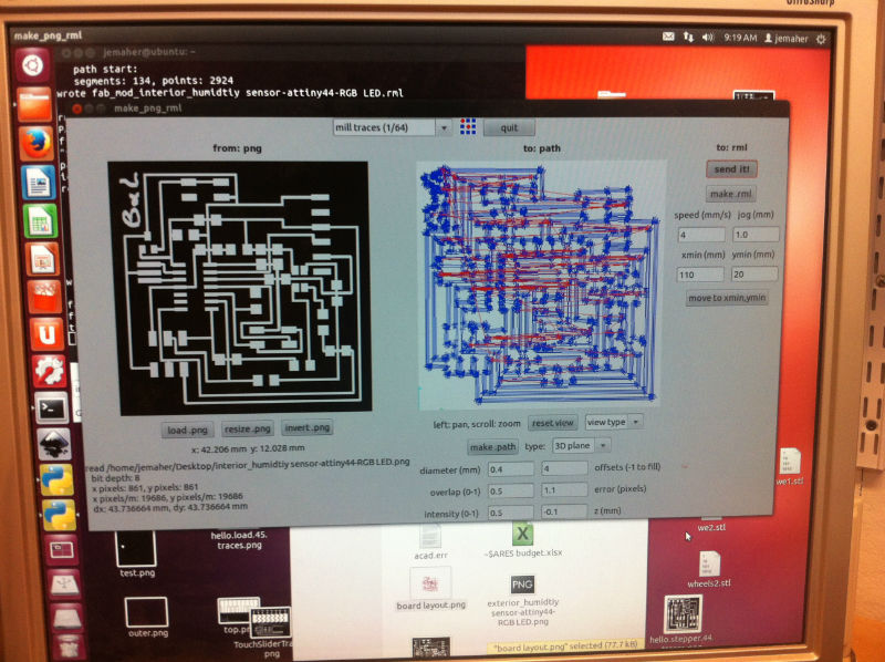
NOTES: mid part circuits get connected, cutter separates them (not a good idea though, because some remained copper thing strip may create shorts)
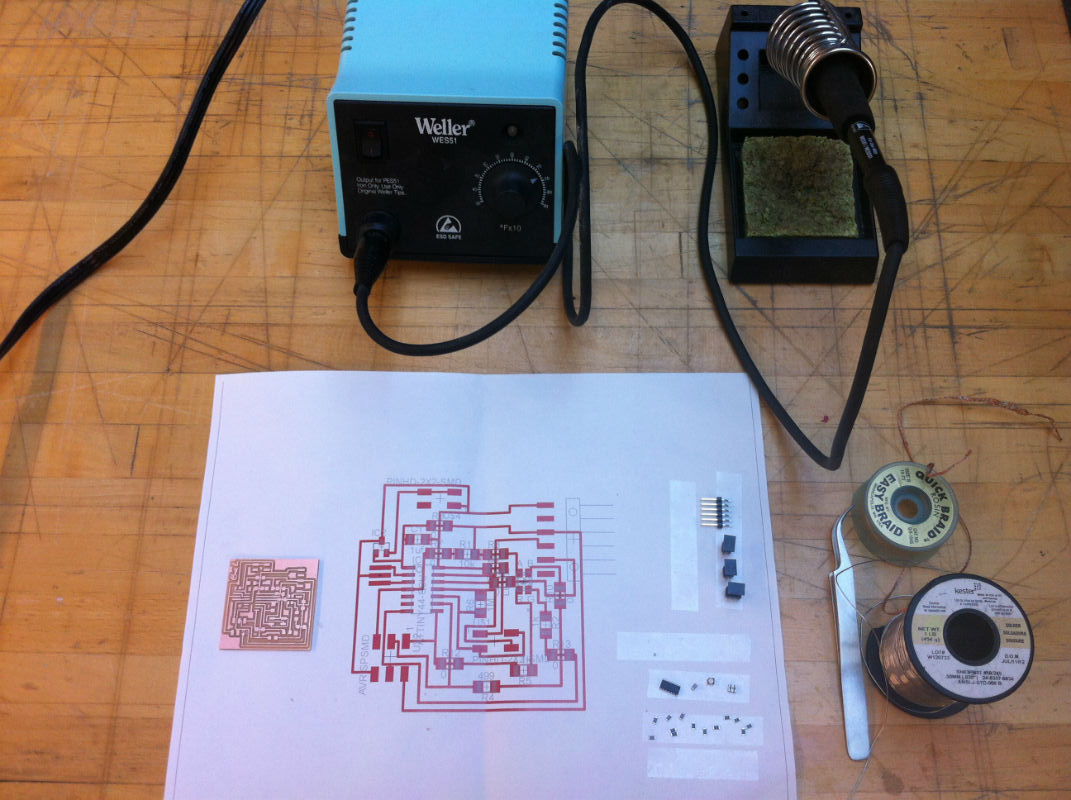
print out the board layout, tape components found from shelf. Soldering sets.
how the board looked like:
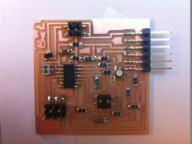
2.2 The board should looks like this!
Re-do is coming.....