Final Project: Localization
The attempt, and I do say "attempt", was to make a wireless localization system. That is, a system that can be used to trilaterate or triangulate the location of an object within a room with fixed beacons and a wireless communications technique." Years ago I had read sections of Tom Igoe's book "Making Things Talk," and in one chapter he suggests using radio frequency, RF, signal strength to triangulate position. So, knowing nothing about RF, I thought it might be relatively straight forward...
As it turns out signal strength is dependent on many variables, only one of which is distance. I spent a good amount of time getting the Hello_radio project working and modified to output RSSI before actually doing the research to find out RSSI localization is not really effective. The system has been tried and has been shown to work in the Ultra Wide Band range, but sub-Ghz 434, 868, 915 Mhz is not so effective. Also, I found it difficult to understand the RSSI signal. It is supposed to be Analog, but I was only seeing a digital threshold pulse. Ultimately I ended up giving up on the RF localization and moved to try to implement Ultrasonic Localization. While I was unsuccessful with both systems, I was successful in diving deep into the datasheets of the Atmega328P and the MRF49XA RF transceiver chip.
Below are play-by-play notes of my progress through the project:
Work in progress, running notes
I want to start with a baseline of a working hello radio. I've machined four boards. The first two I lost some pads. I was following the directions to set the cutter diameter to 0.38, however this is too small, which means more trace gets cut than should. I decided this is part of the reason i was losings pads. So on the third I set the diameter to 0.397. Unfortunately, on that one I forgot to load the outline program and i destroyed the board by using the 1/32 cutter on the traces path. doh. The fourth board i cut everything out fine, but then found i lost a pad going to the ground on the MRF IC. But, I think it will be salvageable. So I'm now cutting a second board, since i need some sort of communication network to test. If it comes out okay I'll begin populating the boards.
Some notes:
- Looking at the datasheet, it recommends a ground via directly under the transceiver IC, hello-radio has it off to the side.
- I want a direct read of the ARSSI pin. hello-radio does not pull out the analog signal. In digital mode it is a threshold measurement, not a linear analog value.
definitely worth cutting with sharp cutters. i spent a bunch of time clearing out little slivers of metal.
I've machined four boards. The first two I lost some pads. I was following the directions to set the cutter diameter to 0.38, however this is too small, which means more trace gets cut than should. I decided this is part of the reason i was losings pads. So on the third I set the diameter to 0.397. Unfortunately, on that one I forgot to load the outline program and i destroyed the board by using the 1/32 cutter on the traces path. doh. The fourth board i cut everything out fine, but then found i lost a pad going to the ground on the MRF IC. But, I think it will be salvageable. So I'm now cutting a second board, since i need some sort of communication network to test. If it comes out okay I'll begin populating the boards.
Placing Parts a note.
soldering the tiny 0603 parts near the antenna. they float away fast. it's best to put a drop of solder on opposing ends so heating up one component doesn't make the other one float away.
New tip on the solder iron makes a HUGE difference. i was finally able to get a "drop" of solder on the tip and heat transfer was lightning fast (well almost). this really worked super well.
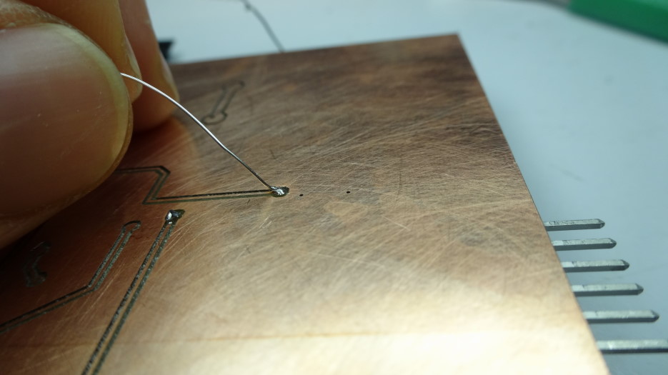
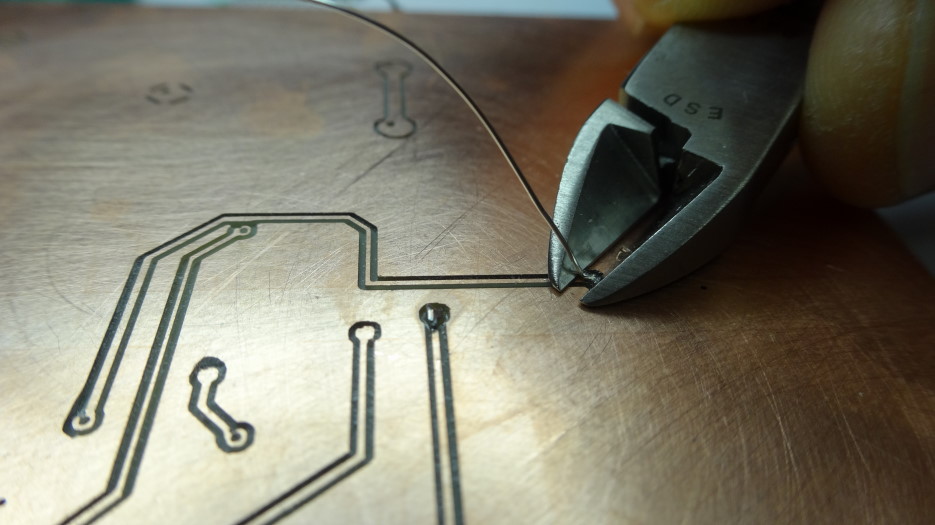
Soldered everything. Vias I did by sticking solder through and melting on the groundplane side. I then melted the solder to the front side. This is kinda risky. Better to strip a wire, pass it through, solder it on each side, then trim it down. this way you don't risk melting away the solder from the middle of the board, since it is not inspectable.
Video
Programming
Now to try programming
I went to Amir's website:
While in the directory with all of your files type:
make
note: firefox/windows downloads makefile and turns it into makefile.txt. avrdudeI want to start with a baseline of a working hello radio.
I got an error:
avrdude: Device signature = 0x1e950f

      avrdude: Expected signature for ATMEGA168 is 1E 94 06
                    Double check chip, or use -F to override this check.
Looking at my chip, it's actually the ATMEGA328P. I should've checked this, the drawer I pulled the parts from must have becoming mixed up, or I must have become mixed up. Luckily these two chips are nearly the same. now i just have more memory. But i need to update teh makefile.
uncomment line 6, and comment line 7 in makefile MCU = atmega328p #MCU = atmega168
Success with loading the data onto the chip.
my ftdi driver stopped working, i was hearing a triple beep(bounce) when i plugged it in and got no simulated serial port. I reinstalled the drivers and it is working again.
The system wasn't working. I noticed I was using an 8mhz system and the make file was programmed for 16, so I commented out line 16 and made a new line setting the freq = 8000000
I then received notification through serial that the chip was alive. i uncommented the printf statements inside hello_radio.c to find out what was happening
it looks like i get all the way into the code, (line 787, where we wait for a receive packet from a second device. so now i need to populate a second device.
Made a second board. it works. well the same as the previous one.
433mhz is a long antenna. so i updated line 94 in the code to switch to an 868Mhz band, since that gets me a decent antenna lenght of 8.6cm.
i think one of my transceiver crystals is not seated correctly. i'm not seeing a signal off of it on the sccope.
yup, i reflowed it with the heat gun and now i'm getting a 3.3 oscillation. and i'm getting communication. sweet!
SPI Now I need to understand how the uC is working with the MRF chip. From what I've read, i can just use SPI to communicate with the MRF. The MRF then takes care of all of the RF stuff. The pins necessary are SCK, MOSI (SDI), MISO (SDO), SS. I send two dummy bytes. Then the data. Then end with a single dummy byte. That seems to be it. There's a great explanation of SPI by Nick Gammon.
The question I have is: It is unclear to me the difference between send/receive data (rf transmission) and how do i adjust the settings on the MRF chip itself, such as set frequency and such.
Okay, so the deal is that with SPI you start the transmission then you can send command codes that the device is listening for. In some cases there are also additional pins to allow it to enter setup mode. In general though, there are specific command codes that are sent that then enter into special access mode for the device. Then the specific settings for that command are sent. In other modes you just request or send data to teh device.
once I get comms working, then i need to pull A_RSSI into a pin and then send that value through to the primary receiver. err, i need multiple beacons to receive values from each addressed node and then each beacon's reading needs to be accumulated somewhere and some math needs to figure out where the node is located.
hmm, need to figure out how to address individual transceivers. this link might have been helpful to try to track down more info about addressing multiple devices.
The way to manage multiple nodes is to put them on different frequencies all centered around the band your antennas is matched to.
To set different center frequencies we can set the register CFSREG <11:0> . there's an eqtn on pg 26 of the MRF datasheet. To set the register bits you need to mask and combine bits. I found this explanation helpful use this:
value =(value &~mask)|(newvalue & mask);
mask is a value with all bits to be changed (and only them) set to 1 - it would be 0xf in your case. newvalue is a value that contains the new state of those bits - all other bits are essentially ignored.This will work for all types for which bitwise operators are supported.
try sending more data. - works
figure out how to setup ADC on chip, again.
read ADC data
send ADC data, and identifier address - not entirely sure if i'm sending decimal data, maybe need to convert to string then send?
i need to figure out RSSI values.
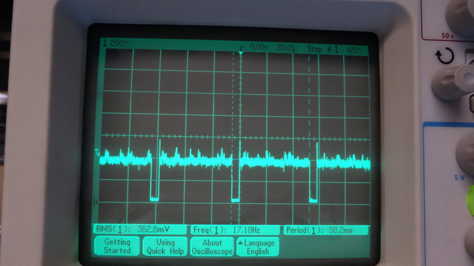
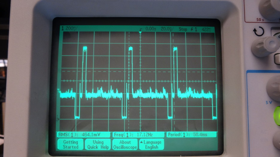
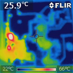
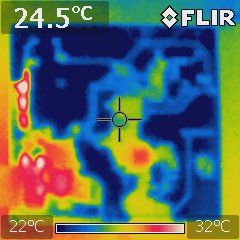
When i scope the RSSI pin 15, I get a square wave value with a frequency of about 17hz, a DC offset of 400mV and a zero value for about 12ms of the 58ms period. When i have a second transceiver going i get a peak up to about 1000mV for just a moment before the 12ms zero and the return to the 400mV offset. I was assuming the RSSI would be a relatively static signal. when i move one transceiver to the other side of the room and even try to shield it with a steel can, I don't see a change in the RSSI signal.
I'm curious if maybe I am missing something??
Also, it seems like the center frequency HEX declarations are maybe incorrect in the code provided by hello_radio.c. From my understanding of hex (which could be wrong), based on the eqtn 2-2 on pg 26 of the data sheet the CFSREG should be 0x640 instead of 0xA640. although it also seems to not matter since it is possible to send/receive strings of data with those settings.
#elif  defined(BAND_868)

#define FREQ_Band        0x0020        // 868MHz

#define _CFSREG           0x640    // Center Frequency: 868MHz was 0xA640
RF localization does not seem feasible.I've spoken with a number of people who have said it is limited to about 3m resolution due to the number of dependencies of signal strength. Forums also mentioned that it has been shown to not be effective
So, i need to re-evaluate my project.
What are the core principles I want to demonstrate:
- Localization? - ultrasonics, possibly with RF for synchronization. figure out ultrasonic circuits. level sensing? not now. do some math to trilateration.
- cybeernetics? - IR notification. could be a sending unit that tells a robot the cup is empty.
this would require level sensing, and possibly a dumbot to track down the cup. to make it interesting. - RF communication? - make a beeper to send signals.
this is the quickest way to completion. get LCD working, button input, make a box
A more effective method of localization is time-of-flight. I found a paper where they use an RF signal to synchronize beacons and receivers. The receivers then listen for the first chirp and calculate time. This removes the reflection issue, somewhat. also, if i have beacons that are elevated it will simplify the line of path. Each node can record the values it hears from the beacons and then send that data to a homebase where the trilateration calculation is done. we should then know where everything lives.
So this seems cool. So now I'm switching gears and attempting an ultrasonics systems.
Now looking at datasheets it seems that to drive the ultrasonics we need a 30V source. later I found out that I can just drive at 5V with more limited range, but I didn't realized that at the time, so I went ahead with the following:
Boost Converter.
I can make one with an ATtiny44 - use the motor driver code. Some helpful links: Boost-converter eqtns. Boost-Calculator. Schematic
one version another this is the one i used mostly
TransmittingSo I can make a boost converter to generate 30V from a little 3.3V battery. That's cool. It's about charging a capacitor with an inductor and switching. it actually is the same principle to how motor/generatores work.
Receiving Receiving transducer will ge generating mV signals so I need an analog amplification stage, with an op-amp. Then it's recommended to make a inverting schmitt trigger with a second op-amp to set a threshold and trigger so that the microcontroller receives digital signals from the ultrasonic pulses.
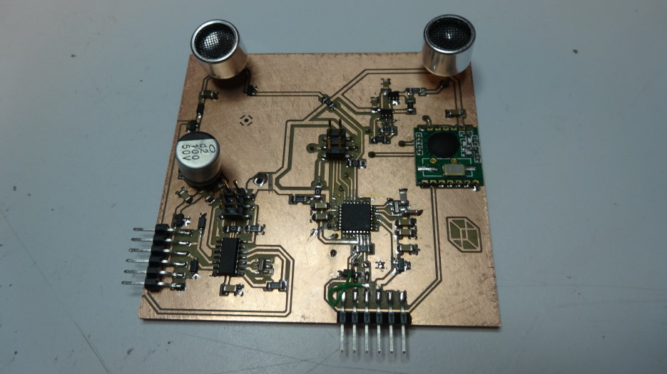
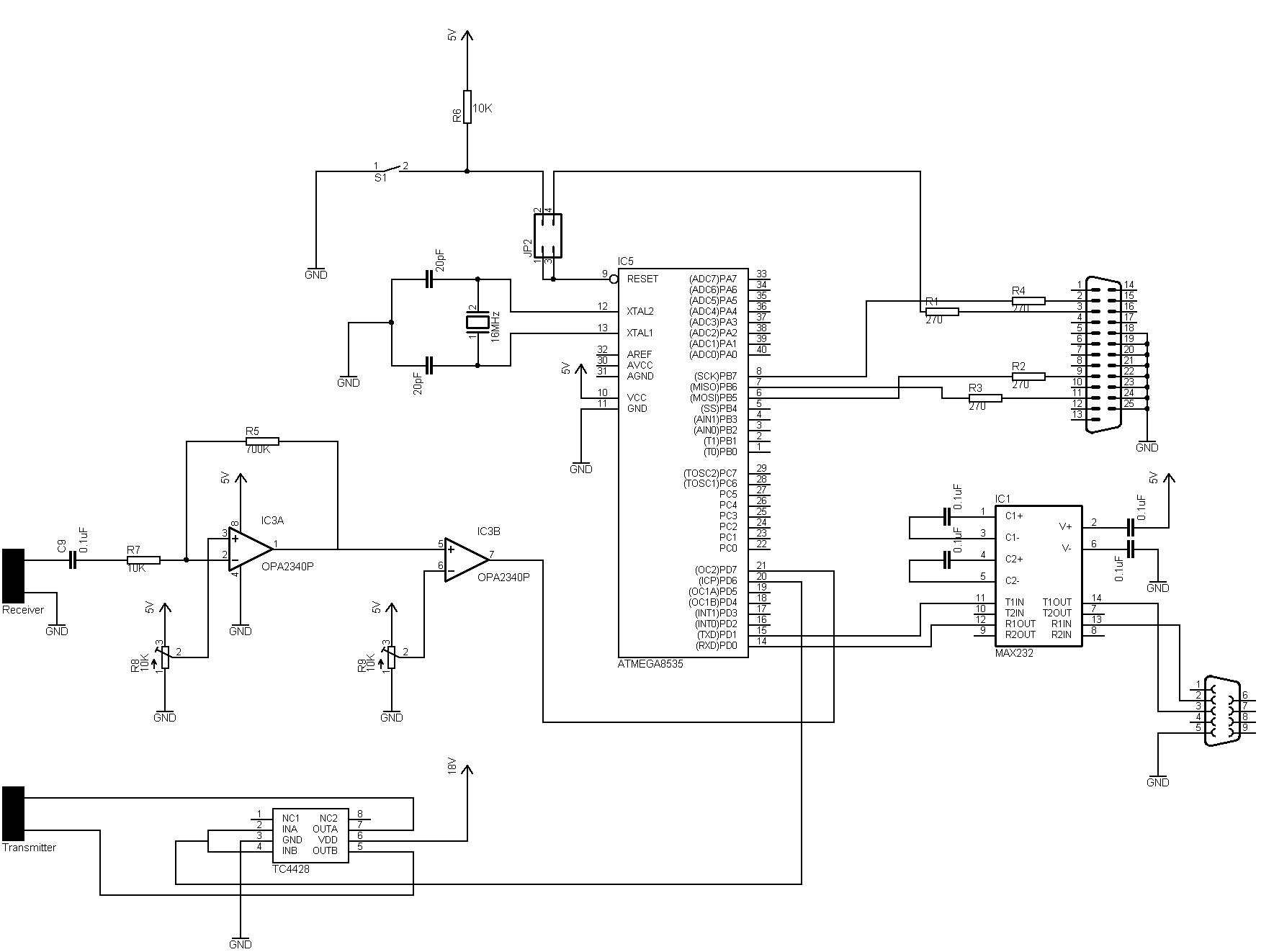
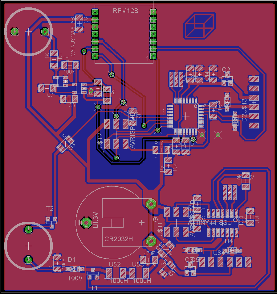
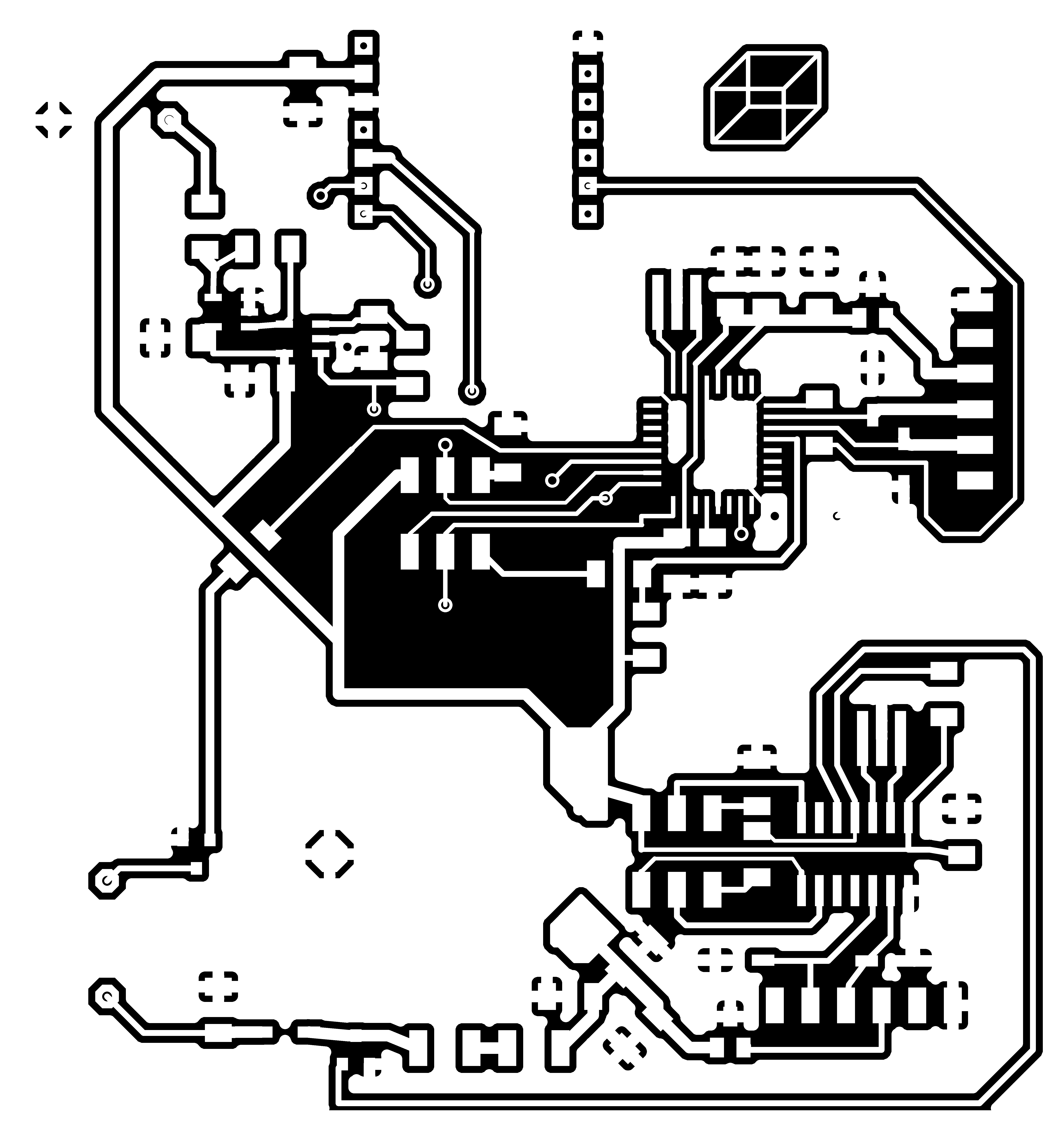
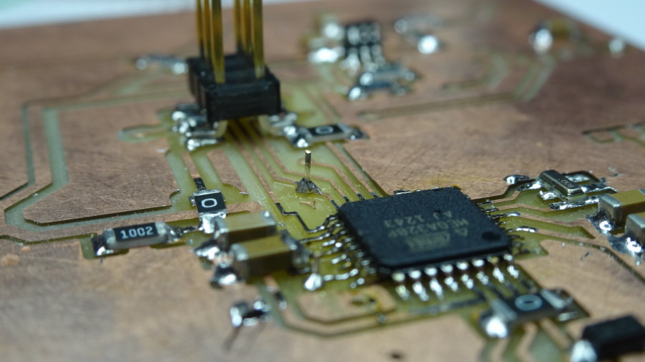
The board includes a boost-converter to drive the transmitter at full power. an attiny44 drives the switching of the boost-converter. Then there is an atmega328P that drives the 40Khz ultrasonic transmitter, talks over SPI to an RFM12B RF transceiver operating at 434Mhz, and also listens on the ultrasonic receiver. This is all to be battery operated. The idea from the paper is that different agents can become beacons and so you can have moving localization information with the group. In my case i can have fixed beacons. The fixed beacons don't need ultrasonic receivers, only transmitters. The agents only need ultrasonic receivers. So this board demos all capabilities, but would be split into smaller boards for cost and packaging constraints. I ended up making it a two sided board, which mostly worked, although alignment was not perfect.
Board files are here:
holes
outline
bottom traces
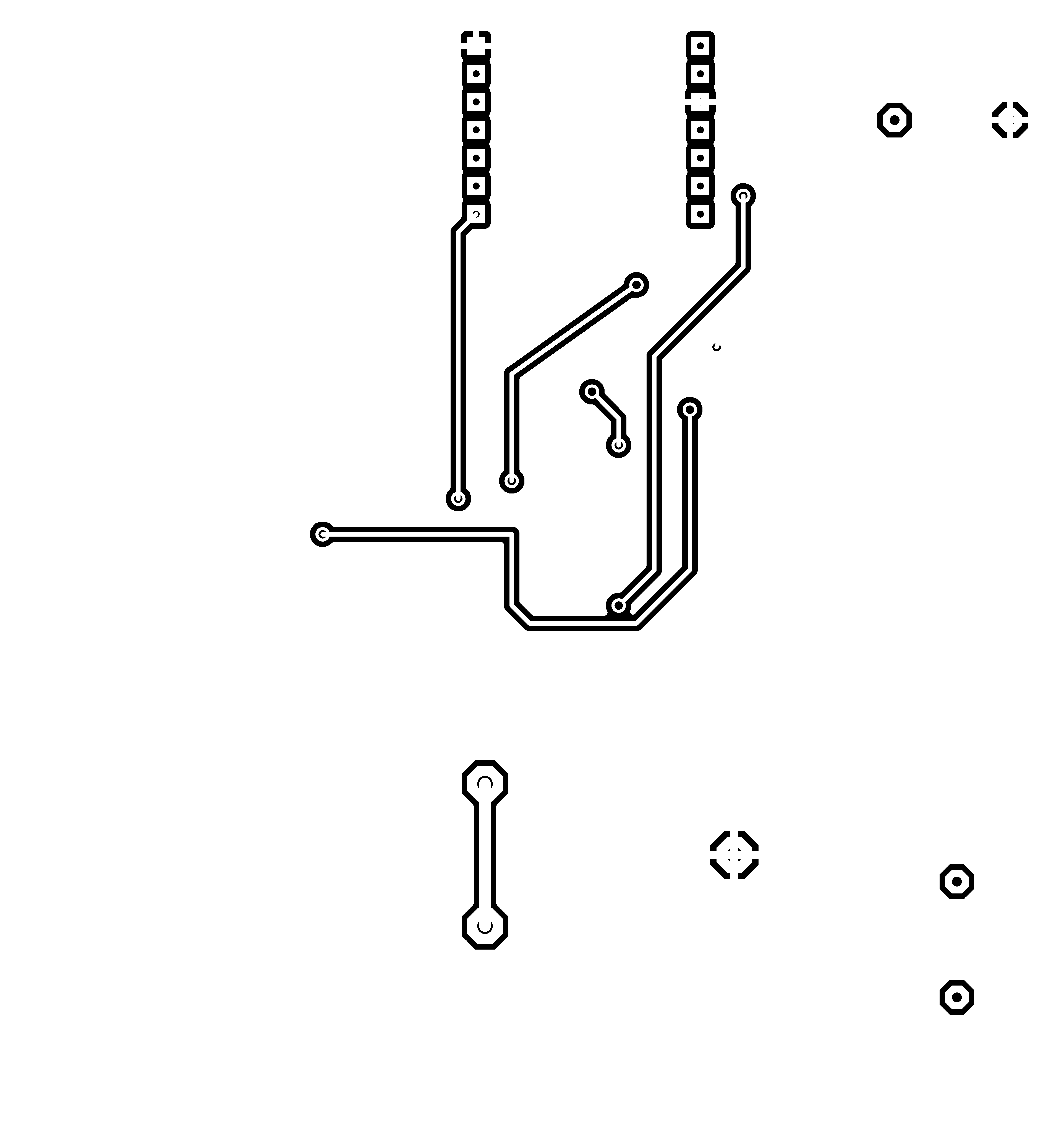
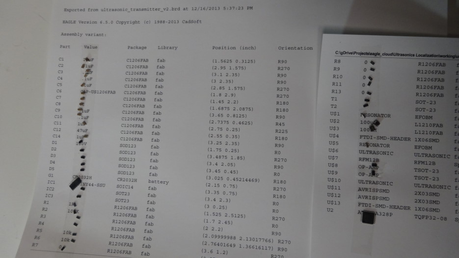
I like to lay out all of my parts before i start soldering. I export the partslist from eagle then put down some doublestick tape.
Looks like the 47uF cap was also not happy, it's only rated to 16V as it turns out, and I was charging it up to ~30V. So i removed it.
I ended up just using the arduino example code "fade."" i used arduino to drive PB2, aka ledPin 8. this works, i am now with PWM=150 putting out 29V +/-.5V. adding some capacitance now. added 10uF, now at 27.8 +/-.05V. increase pwm to 200. tried increasd PWM freq by setting
TCCR0A = (0 << CS02) | (1 << CS01) | (1 << CS00);
looked to wiring.c in arduino to find settings. also tried
//cbi(TCCR0A, CS00);
//   sbi(TCCR0A, CS01);
//   cbi(TCCR0A, CS02);
prescalers did not seem to work as expected. doesn't go faster than 488mhz, prescaler 64.
whatever, moving onward.
oh.
no.
my power rail is oscillating at the driving frequency. right. i need to decouple the power lines. giant capacitor??? i put a 100uF and it helps smooth, but Vcc is still at 2V instead of 3.3. but the boost converter does work. so that's a win!
Trying the atmega328P. bootloader not loading
having trouble with power. only getting 2V. put the regulator back on. still only 2v. cut power line shared with boost converter, still 2V. replaced regulator. 3.3V. okay. bootloader will now load.
error during upload:

Binary sketch size: 1,080 bytes (of a 30,720 byte maximum)

avrdude: stk500_getsync(): not in sync: resp=0x00
scope on the oscillators shows 400mV and 600mV on different legs. will add capacitance at 22pF per datasheet recommendations. Does not seem to help.I've run out of time...
I didn't do a mechanical component for the end of the semester because I feel that I already have mastery of that topic since that has been my career for the past five years. practice with electronics is why i took this class. While my final project was not a total success in such as way as being totally done and working, it was a fantastic success in that I have overcome the hurdle of throwing together a board. I now feel comfortable hopping into Eagle, throwing together a board, designing components from scratch, machining and stuffing the board. I still need to work in programming and interfacing further. and obviously power management on the board. I feel quite content with my progress and I am excited to have built up enough momentum to carry me into many more projects.
Thank you Neil for a great class. It's really the ultimate learning experience, the pressure to drive forward, with the flexibility to choose our interests and the crowdsourced support from previous and current students. It really is a model learning environment.
thanks.