Project 6: Molding/Casting
Come up with something worth molding, cut the mold, cast a different material. That's the task. I wanted to followup on an idea Jonathan Ward and I had discussed while he was developing the Othermill. We visited a blowmolding factory and started discussing the possibility of designing blowmolded mill frames. The thought occurred, what if we were to design hollow molded structures that could be shipped and then filled with water or concrete by the user to increase the mass of the system. Milling machines want to be massive, as I mentioned in a couple weeks ago during Make Something BIG because you want the natrual frequencies of your machine to be far away from that of what you're cutting and this can come from making a massive system that has inertia to stay exactly where it is and not vibrate. But shipping a massive system is not cheap. So why not ship a lightweight product and massivate (that is now a word!) at/by the consumer?!
This project is a simulated wall for an MTM machine that is not blow molded, but rather is the idea turned inside-out. Concrete, or well Tuf Stone in this case is cast into a machined foam shape and a plastic insert is molded into the gypsum material. This allows a rigid wall structure with a plastic insert molded feature commonly used in the MTM for shaft alignment, something ceramics are really not good at - ductility. One other interesting thing that could be done and I may or may not be getting the benefit of this with the material I chose; it would be interesting to impregnate the cement with an energy dampening polymer such that the structure not only resists vibration but also dampens away vibration energy - this is something that is sometimes done in precision machinery.
The Process
I designed a multi-body part in Solidworks that included the insert, features for holding square nuts and passthrus for screws. I included taper on all of the shearing surfaces to help the part (hopefully) eject from the mold. This of course makes machining much more difficult on a 3-axis machine unless I used a taper endmill (which I did not). So first step was to machine the molds.
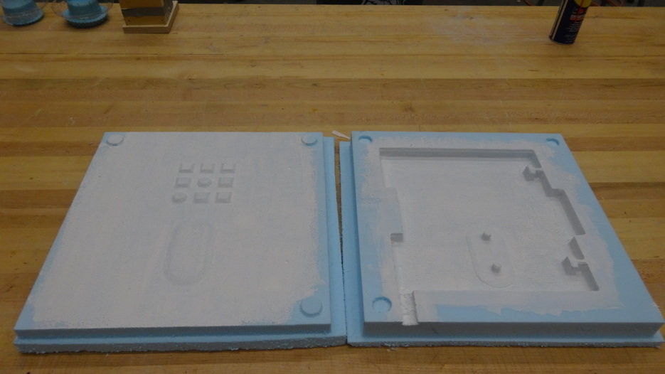
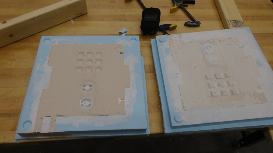
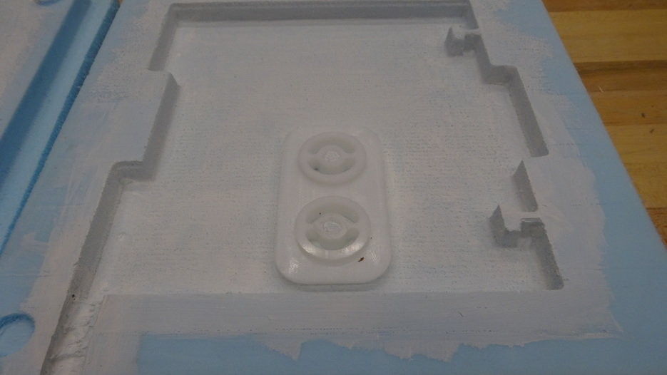
I then covered the foam in Gesso in an attempt to seal the foam surface. This is the white coating seen above. I had hoped it would be sandable and help reduce the porosity of the surface to allow part removal. Perhaps if I layered half a dozen coats of gesso this would have worked - I didn't spend enough time perfecting this part as it wasn't as interesting as a part of the process for me as the machining/fixturing.
I took this week to get the workpath flow to allow me to do more interesting things with the CNC machines than the standard ShopBot software, Partworks, allows. Turns out we have some licenses of HSMWorks in the shop which is a CAM package that ties directly into Solidworks. It is much easier to use than MasterCAM at the cost of some customability that I am not personally interested in (yet anyway). So after a little going back and worth with the distributor we managed to get the license and subscription stuff worked out and by late in the evening I was up and running with not only a post-processor for the ShopBots but Charles Davis at NextGen also sent me the post-processors for our 5 axis Hurco mill and one that should work for our Harrison CNC turning center (lathe). That was very nice, and he also left a nice note after helping me saying "make something great with this." Oh we will...
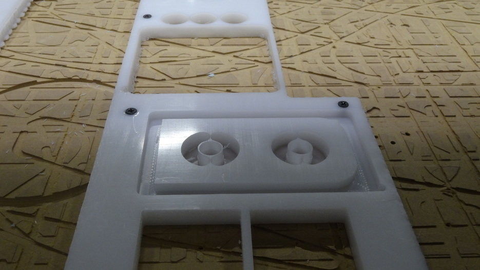
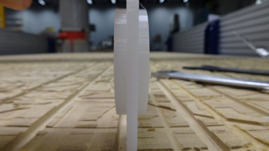
HSMWorks debut was not for too fancy of a part though. It was simply a two sided part that was difficult to do with Partworks because in 3D mode we don't have control of following specific contours, it just rasters the whole thing. The contour control allowed me to machine one side of the part. Then machine a pocket in another piece of sacrificial material that I used as a fixture. So that I was then able to flip my part over, hold it in the fixture and machine the second side. Each of these steps are shown below. I did have a little trouble, I couldn't find the correct collet holder for an 1/8" cutter and ended up using a 1/4" cutter, but I forgot to change to the tool on the first cut. so that is what is actually shown in this first picture below (noticeable by the thing webbing. I left about 0.15mm of a floor on the bottom as a web to hold the material in place. Next time I will increase this because it was a bit uneven and I had to end the program early so my part wouldn't get flung away.
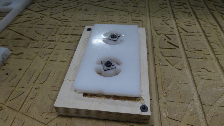
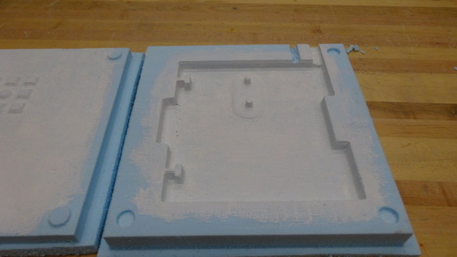
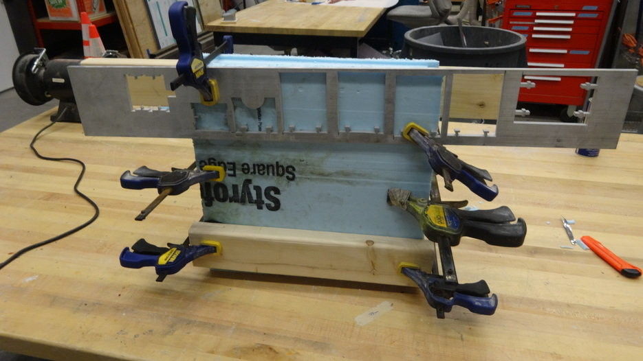
Below the insert part is located on pins I had machined into the mold to locate the component. There are depressions on each side of the mold to hold the insert in place and allow for thicker walls in the bulk material. I also included locating features to help align the two mold sides. The maching wasn't perfect on these but the foam is forgiving.
Vents are important, there must be a pour hole as well as a vent hole so the air has somewhere to go. I initially intended to machine these, and then forgot about them during the design work and did not machine them. So I cut them out by hand. I put the vent near the pour sprue as close to the top of the part and alongside the vent to allow airbubles to escape.
Securely clamped the two halves together in an attempt to prevent leakage. This seemed to work okay.
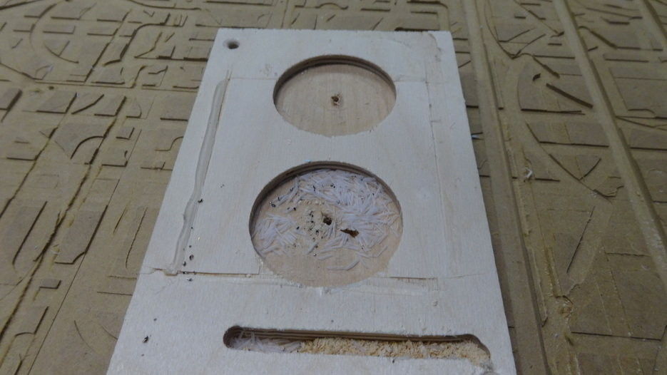
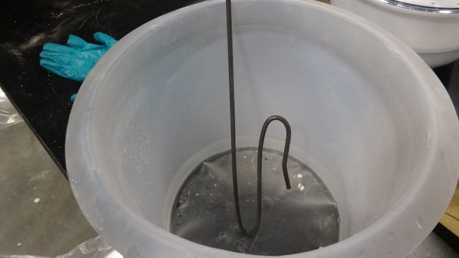
Mix, degass, and pour. I made a makeshift mixer with some bent steel rod and a hand drill. This mixes well, but of course introduces airbubbles. I was able to place the container of Tufstone in the vacuum chamber and with some vacuum and shaking I think I removed most of the bubbles. I then poured the material and it seemed to go fairly flawlessly with a little shaking a poke or two to clear the sprue.
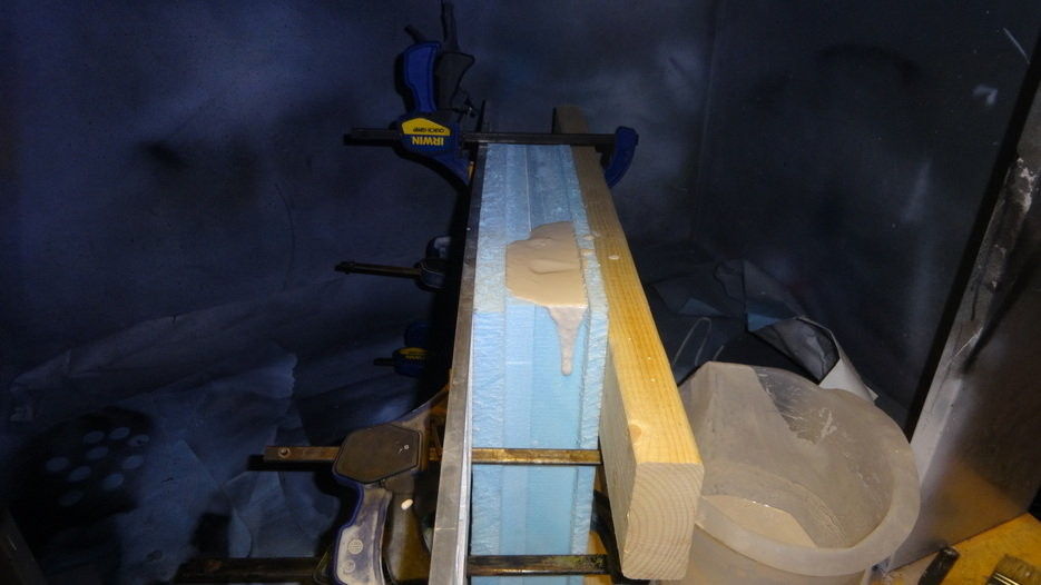
I got eager and opened up the mold after a couple hours, and it was not done yet. I had checked the container I mixed in and everything was nice and hard, but I guess the heat and moisture changes were different inside the mold than outside. So I closed it up and will check again in the next day.