Electronics Design
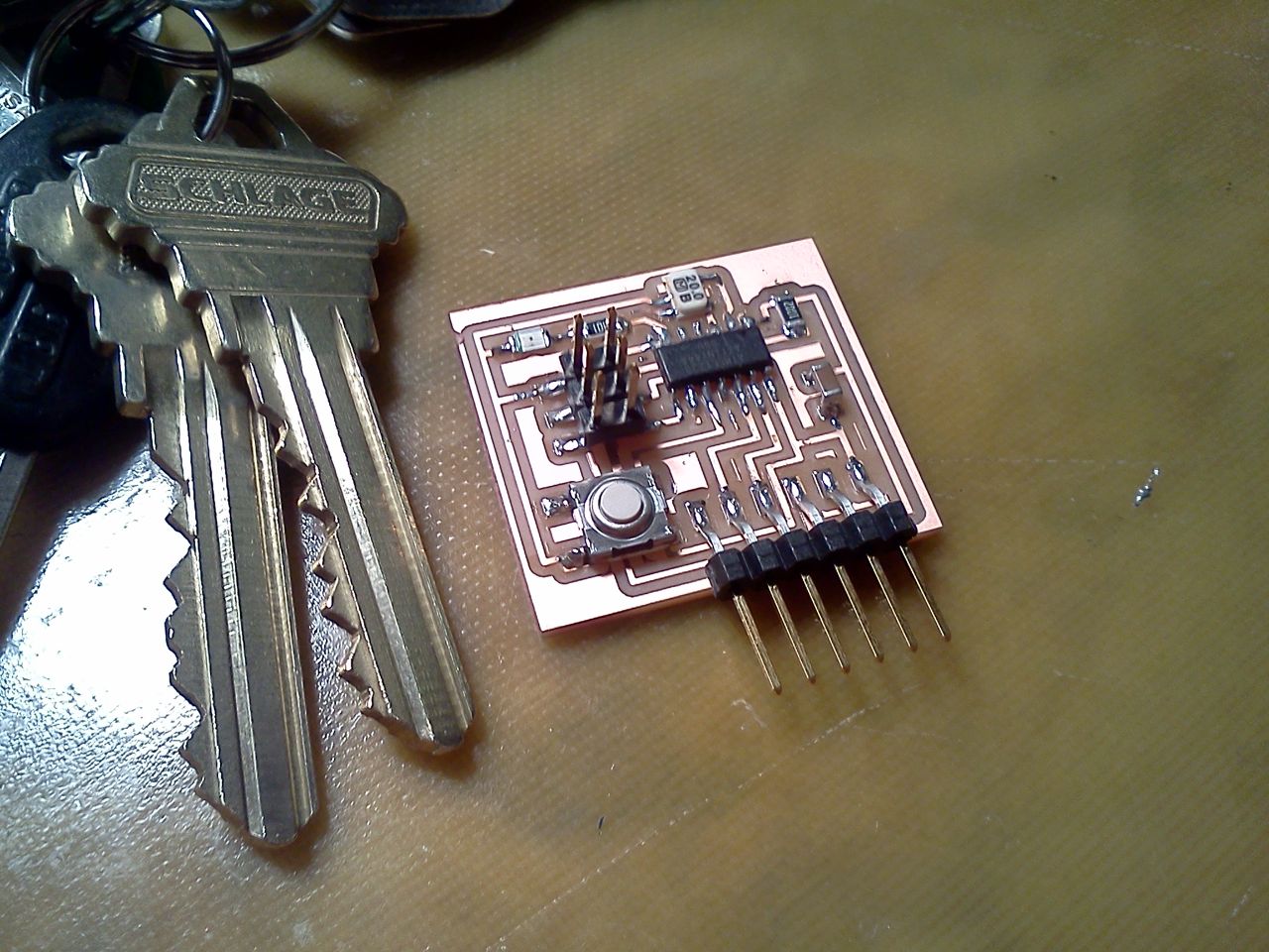
For Electronics Design Week we used the EAGLE design software to describe and fabricate a simple PCB. This biggest challenge for me was learning EAGLE's and it's many design quirks.
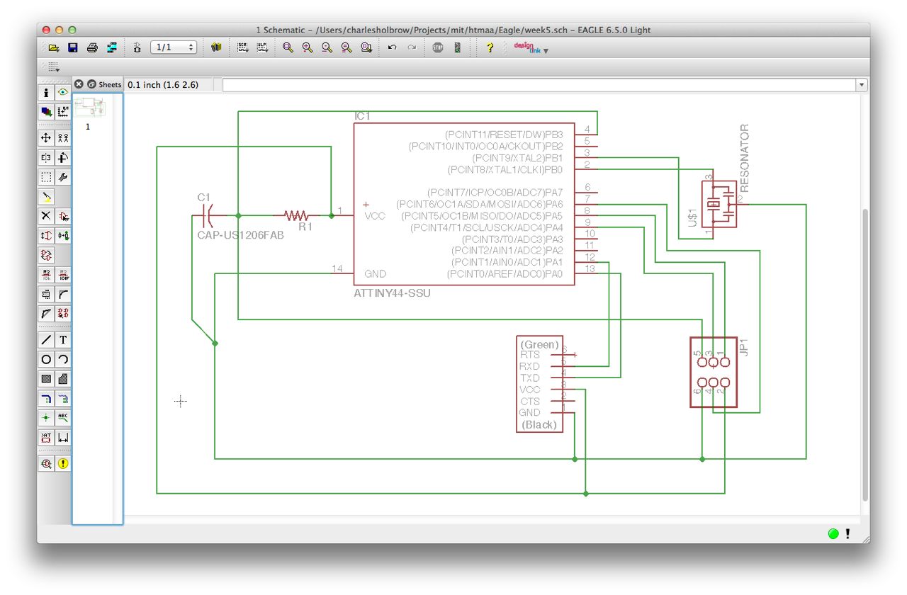
Creating a schematic in Eagle - Important:
- When drawing wires, you need to explicitly tell EAGLE where wires should intersect. Use the "node" feature to indicate that wires intersect.
- To Draw a connection on the contact of a pin, you need to draw the connection exactly on the tip of the component connector.
- Because the location of wires is so precise, use mouse-wheel zoom to save time when drawing.
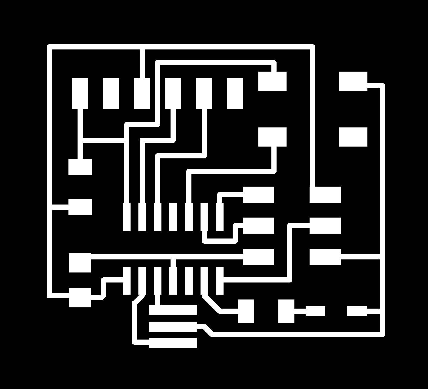
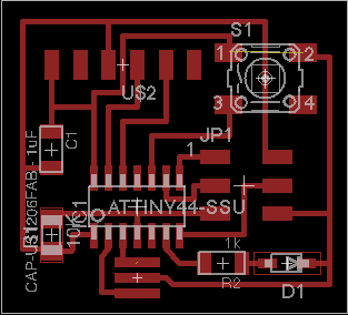
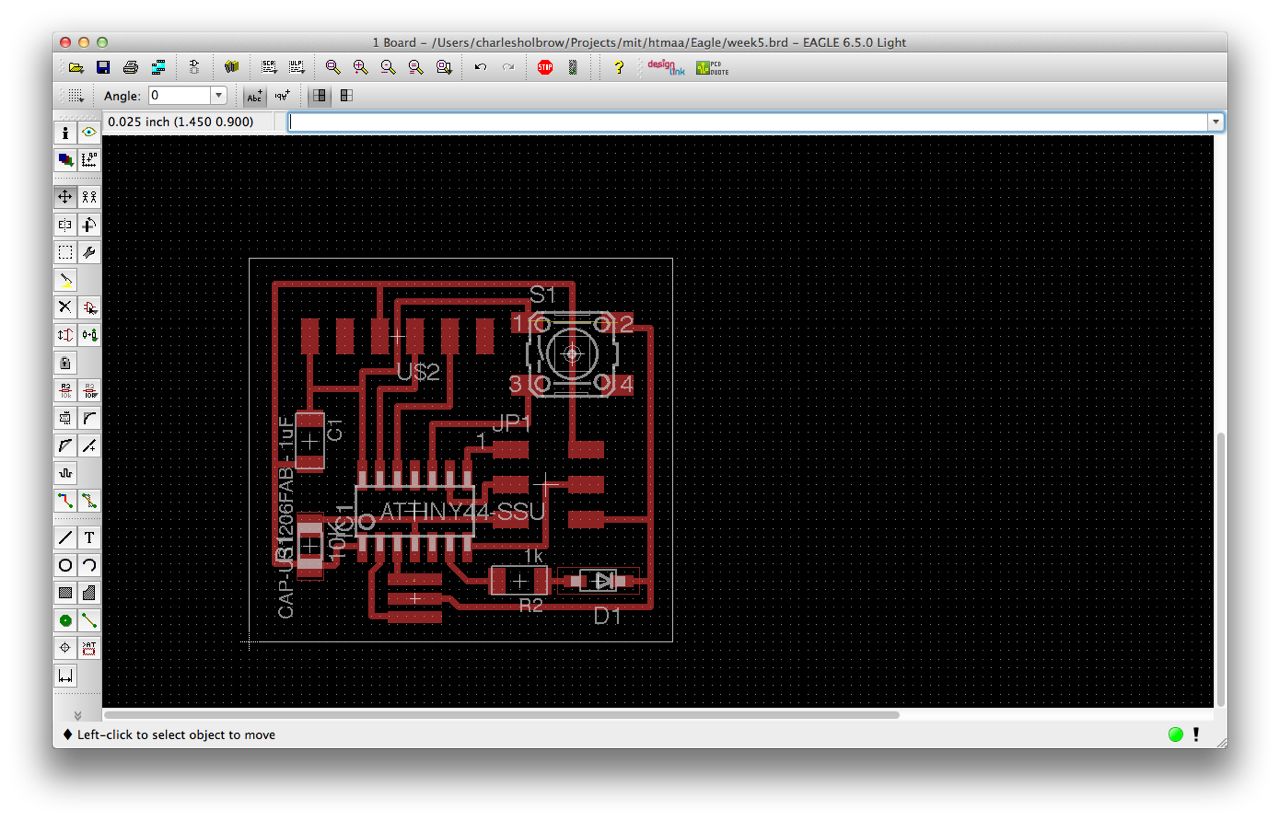
Design the PCB Layout - Important:
- When iterating on trace position in the layout view, use the move option to drag cables -- this is usually quicker than deleting them and re-drawing.
- To move a component, you need to click (using the Move Tool) on the plus sign at the center of the component - clicking on the footprints will try to move the traces associated with the footprint
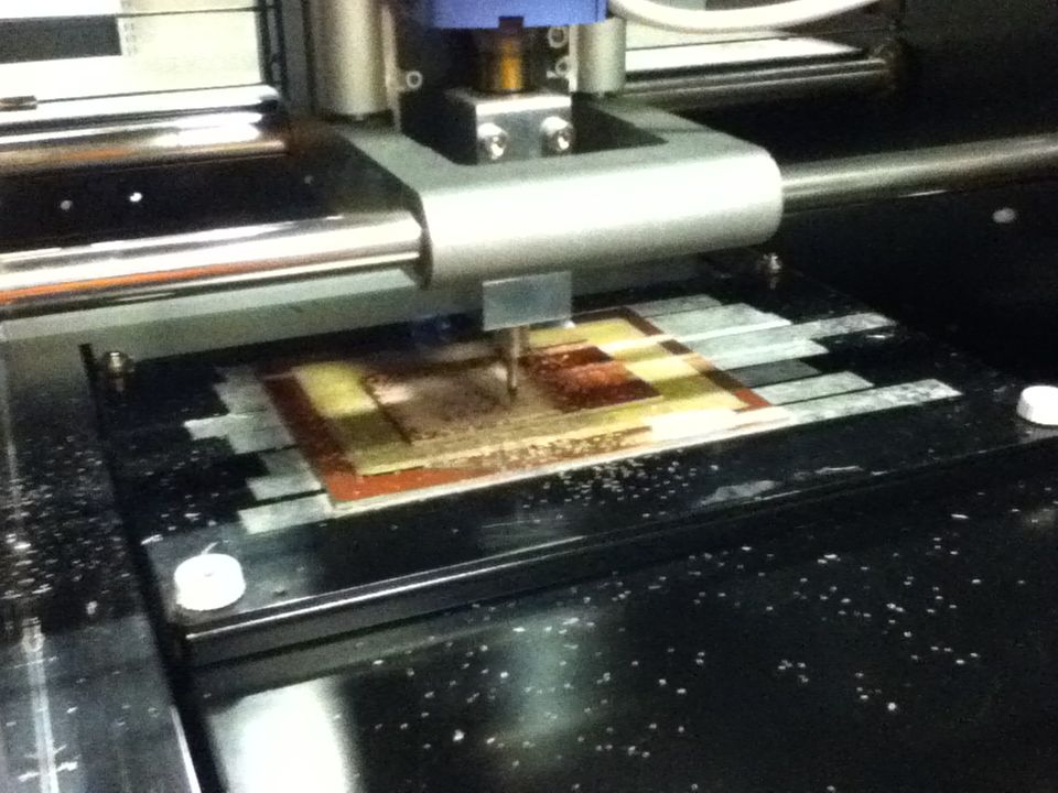
- The default grid size is too coarse for use with the Modela mill. In
View -> GridI set the grid to 0.025 inches, and it worked well. - The Error Checking feature was useful - It makes good guesses as to when traces are too close together or overlapping. To use it:
Tools -> DRC -> Clearance -> (Set all tolerances to 8mil) -> check
Here are files associates with this week's project: