Week 12 Interface and programming applications + final project update.
This was a busy week!. i started working in the final project circuits and design + this week assignment.
Decided to make my color sensor work, i spent 4 days in the lab working, after many failures i finally have a fully functional (well it needs a little bit of redesign...i'll explain later) color sensor.
Since the suggestions from people were "buy one" or look at this "instructable" i decided to learn the hard way and not follow any . i have been working for at least 3 weeks in this sensor and after version 12 is working so with the time i had left i decided to test it with a very simple java interface.
1- design.
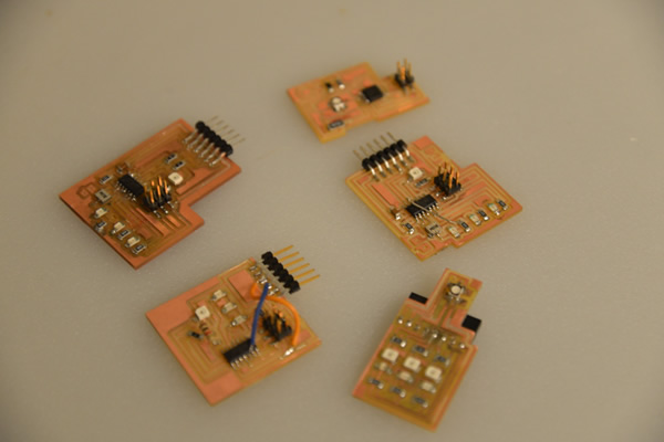
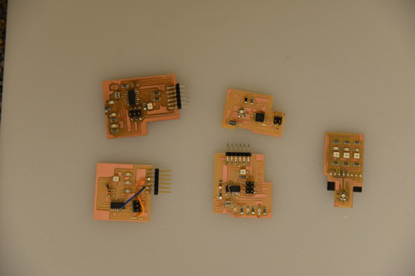
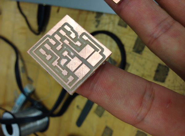
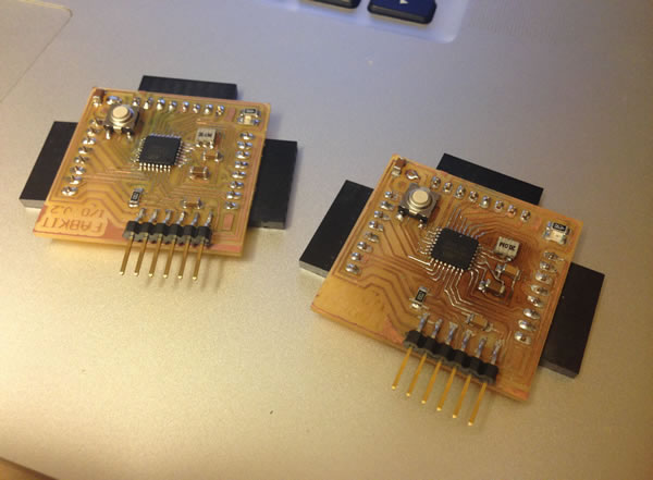
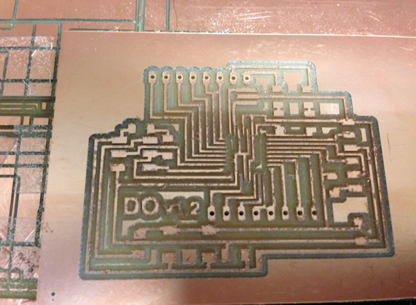
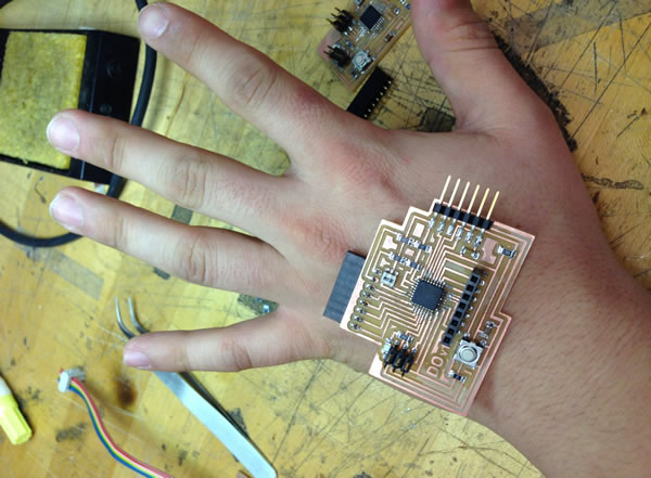
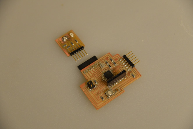
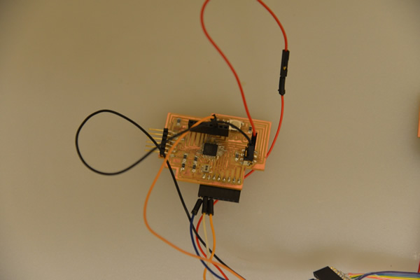
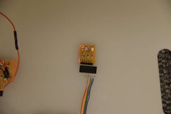
Version 12!!!! it was right , or almost right. following the theory from this website, i started the design of my project. the main goal was to reduce size and leave the most of the components (microchip , resistance, main conectors, etc.) on one board and leave just the essential in a tiny board. in this version i almost didit, now developing the final version (v 13)
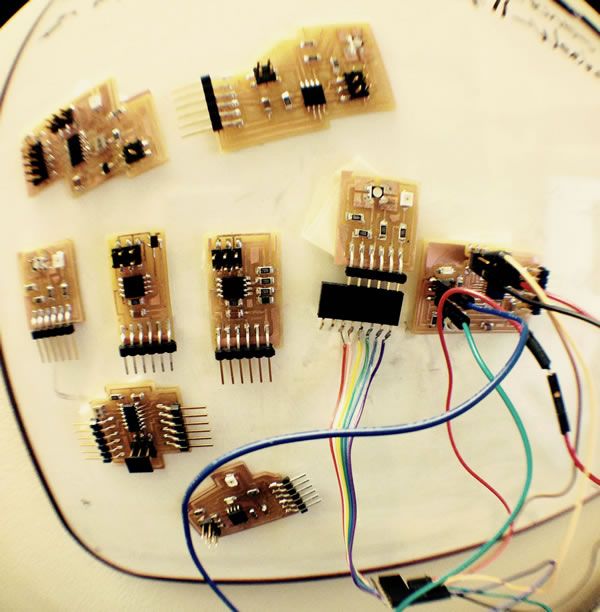
Previous versions of the sensor. lot of time invested , many failures but many things learned the hard way!.
.
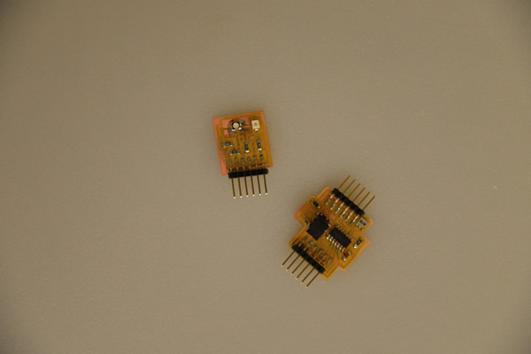
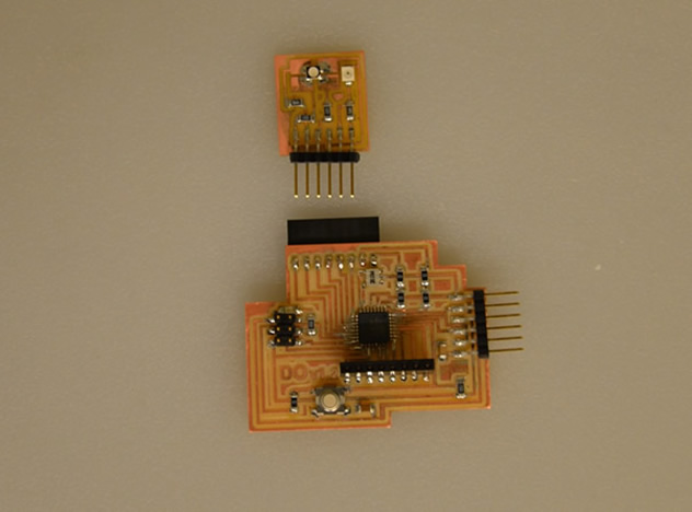
Version 11(thanksgiving day)- attiny and conections separated from the finger (for my final project) - on the right, the size of the board with the basic components, not small enough. can be reduced easily i think.
Because i needed more pins , and the code was too big to fit in the attiny 44 i decided to fabricate my own arduino. i started testing neil's arduino that worked fantastic thanks to the fabulous tutorial from Amir Lazarovic. It was good to start understanding how to build an arduino and play a little bit with the possibilities, the problem is that i still needed more pins so i moved to FABIO. sadly after many attempts and being able to burn the bootloader, the boards i made (two!!!)., didnt worked at all, the arduino was unable to establish communication even after burning the bootloader successfully (need help , because maybe i'm missing something).
Do-Duino.
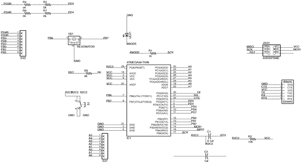
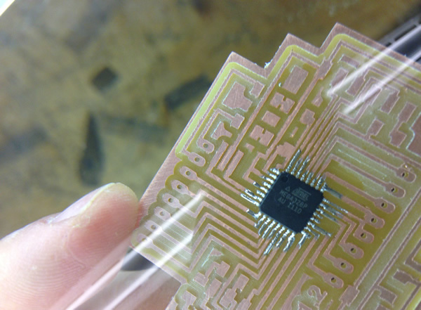
Based on neils board, i redesign the arduino with atmega328 and a 20mhz resonator, again everything worked fantastic. Because i have milled and stuffed over 25 boards this semester, i think im a master in the soldering art :) .
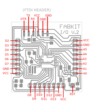
Eagle schematic and pngs
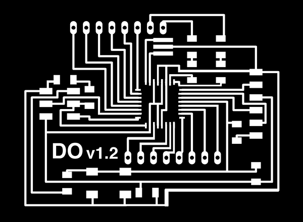

3- fabrication.
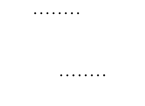
Here some pictures of the fabrication process. milled the board with a 1/64 inches using the fab modules, and a 1/32 " for the holes and the final cut of the board.
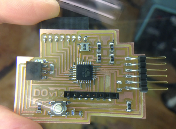
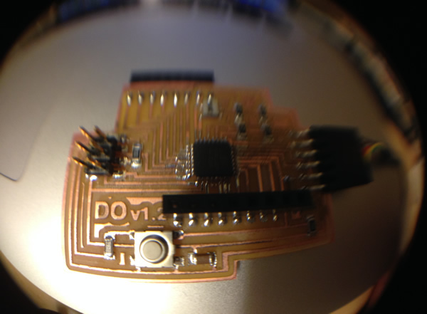
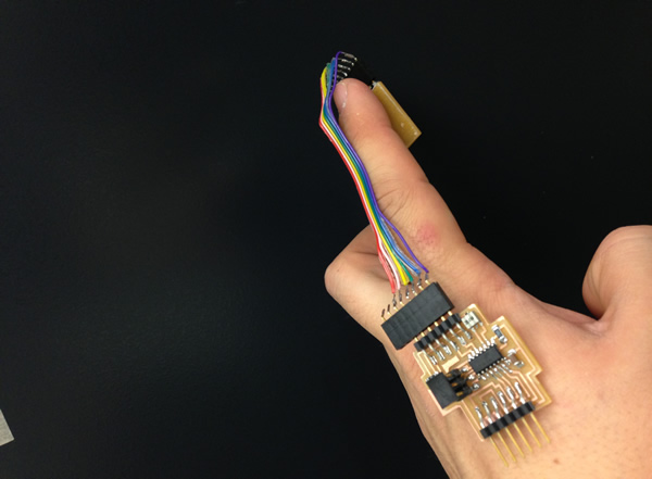
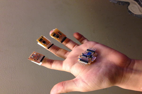
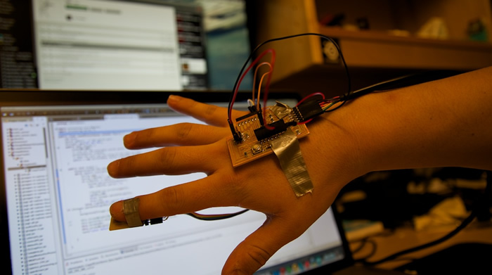
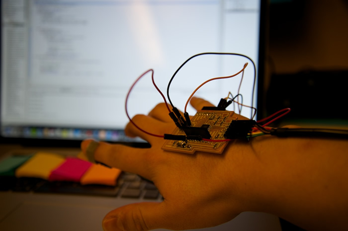
The final board fits perfect in my hand , so i decided to use it as the central brain for all the sensors for my final project!.
The board worked fantstic and it took about 45 seconds to burn the bootloader . i tested it with servos and lights , testing every pin.
burning the bootloader
testing servo motor.
3- color sensor + DO-duino.
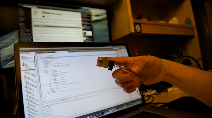
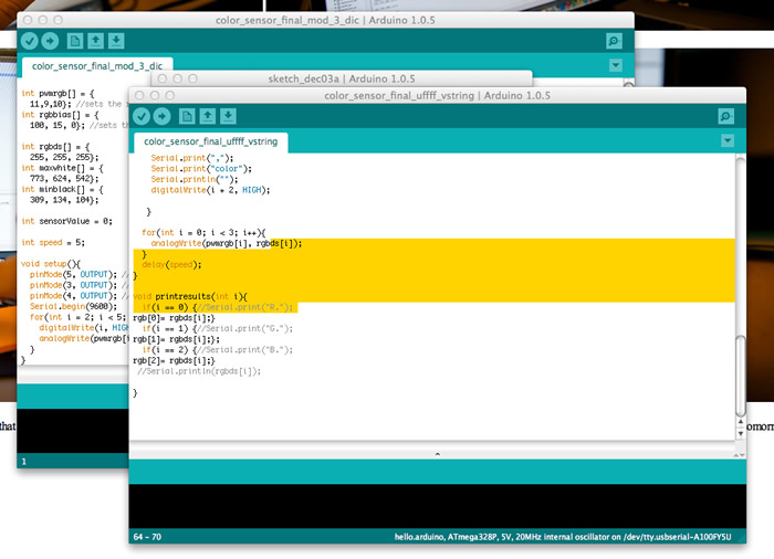
Finally i modified again the sensor, and started working in the most difficult part - making it work by programming it and calibrating it.
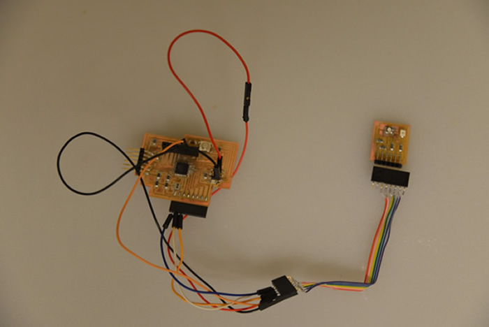
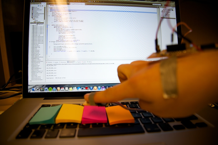
I started with many faile attepmts , no response from the sensor, incorrect values or characters,wtc. I spent all weekend making the code and testing values to calibrate the sensing of colors. nothing worked until today tuesday 3 of december.... i used arduino IDE. i had many troubles with the equations (from the website i posted at the beginning) and with the serial port readings (very little experience in electronics and very little experience in programming circuits... obsession was my allied this time). after 6 hours of debugging my board started returning RGB values!!!!!. i tested it of course with the board on my hand to have an initial idea about using the prototype. it felt great and i was usefull to get measurements and ideas for the final device.
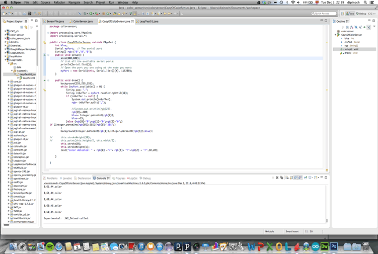
For the interface i made a simple program in eclipse (java) that according to the color it changes the color of the background (after all the hard work i had little time to program something more advanced). i'll post an update tomorrow for sure!.
I programmed the board so it can send the values as a single RGB string as "255,255,255", so the java code can split the values into Red , green and blue.
Video of the sensor working, still under calibration , but i think the results are amazing after all the time that i spent working , figuring out about Atmega 328 functions, re designing from scratch an arduino, making 12 versions of what everybody told me it was an easy sensor, etc. i learned and im proud of the results!!!. now i can move to other sensors to complete my project and focus in the fabrication part!!.
htmaa_week13 from DIGIFAB on Vimeo.
Color sensor from DIGIFAB on Vimeo.
4- Final project first prototypes.
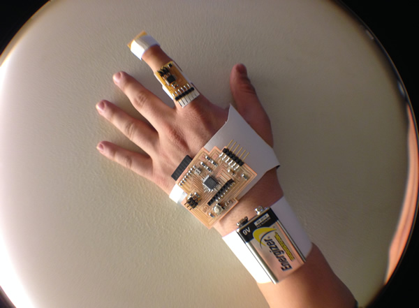
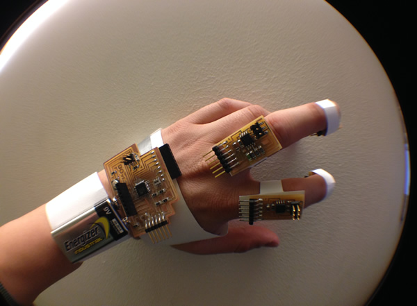
With with some of the circuits ready and working , i started making some paper models to test ergonomics and ideas about how can i make my final project, here some images and explanation about the idea that im working with.
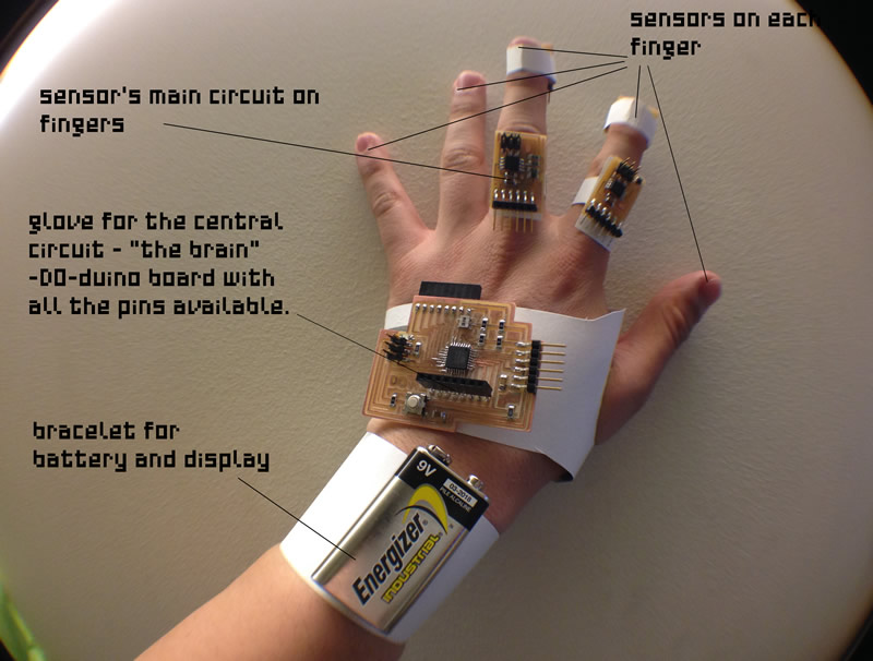
i want to put at least four sensors in the fingertips connected to each sensor circuit, and then connected to the central Arduino board. The board is connected to a battery and possibly to an lcd screen (16x2) that will display values from the sensors.
electronics position diagram.
Fabricated pieces diagram.
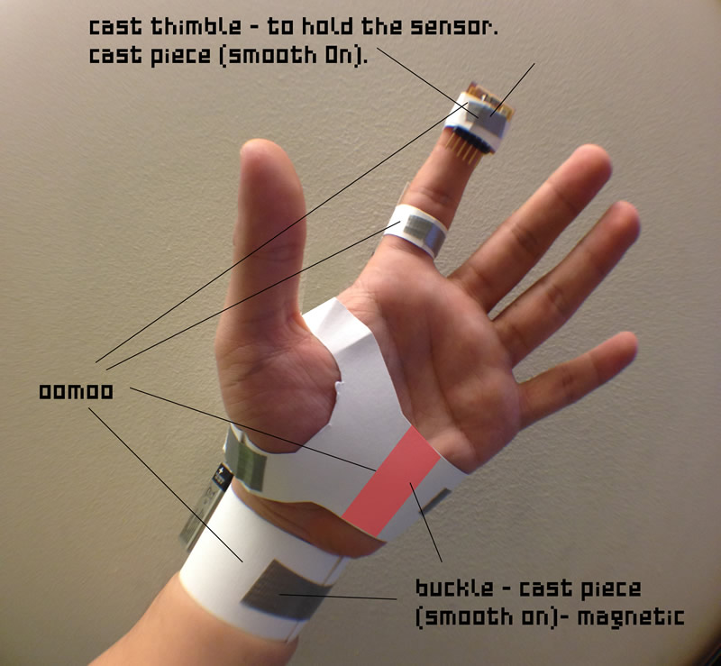
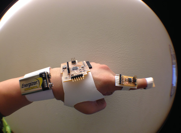
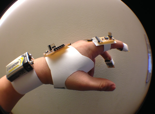
This is the first part of the prototype that i want to fabricate this weekend, i have to make the mold and cast the pieces to fit electronits , magnets and sensors. a lot of work again!!!.
some pictures of the prototypa that gives an idea of the final project.