Geoff Tsai
MAS.863 How to Make (Almost) Anything, Fall 2013
Weekly Projects
Project 13: Interface and Application
Write an application for a device
Project 13: Interface and Application Programming
Write an application that interfaces with an input and/or output device.
Project 12: Networking and Communications
Design and build a network
Project 12: Networking and Communications
Design and build a wired &/or wireless network connecting at least two nodes.
Project 11: Output Devices
Output something
Project 11: Output Devices
Add an output device to a microcontroller board you've designed and program it to do something.
Project 10: Input Devices
Measure something
Project 10: Input Devices
Measure something: add a sensor to a microcontroller board that you've designed and read it.
Project 09: Composites
Make a fiber composite part
Project 09: Composites
Design and make a 3D mold; produce a fiber composite part in it.
Project 08: Embedded Programming
Program your board to do something
Project 08: Embedded Programming
Program your board to do something.
Project 07: Molding & Casting
Design a 3D mold, machine it, and cast parts from it
Project 07: Molding & Casting
Design a 3D mold in CAD, machine the mold out of machinable wax using the Modela mill, and cast parts from it using a two-part silicone resin.
Project 06: Electronics Design
Draw and modify the echo hello-world board
Project 06: Electronics Design
Redraw the echo hello-world board; modify it by adding (at least) a button and LED; cut the PCB on the circuit mill.
Project 05: Computer Controlled Machining
Make something big
Project 05: Computer Controlled Machining
Use computer controlled machining to make something big. Learn how to use the ShopBot to cut plywood.
Project 04: 3D Scanning and Printing
Design and 3D print an object; 3D scan an object
Project 04: 3D Scanning and Printing
Design and 3D print an object (ideally small, about a few cm) that could not be made—or at least would be difficult to make—subtractively. In addition, 3D scan an object.
Project 03: Electronics Production
Make the FabISP in-circuit programmer
Project 03: Electronics Production
Make the FabISP in-circuit programmer. Mill the circuit board on the Modela, solder the components, and program the FabISP using another ISP—even another (programmed) FabISP!
Project 02: Computer Controlled Cutting
Design, make, and document a press-fit construction kit
Project 02: Computer Controlled Cutting
For this project, I wanted to create a set of basic building shapes that could be used to create more complex assemblies. Like LEGO bricks, I wanted the pieces to be abstract in nature so they could create any number of specific forms.
Project 01: Semester Project
Sketch and plan of a potential semester project
Project 01: Semester Project
I want to create an ultra-lightweight, multi-degree of freedom camera rig to bring with me to the outdoors in order to make motion-controlled timelapse videos.
Final Project
Camera Motion-Control
I'm interested in photography and I enjoy the outdoors. I often bring my camera with me to the outdoors: fishing, climbing, hiking. Occasionally I do timelapses outside, but I'd really like to bring a multi-degree of freedom rig with me in order to add some motion to my timelapses.
What's out there
There are several motion-control products on the market. These are often big, heavy, and expensive. A lot of the bloat comes from the desire to make bombproof gear that can push the heaviest camera bodies and lenses. With stiff and heavy frames, these products allow smooth, fluid motion in even the worst of circumstances. And the high prices are fine for professional photographers
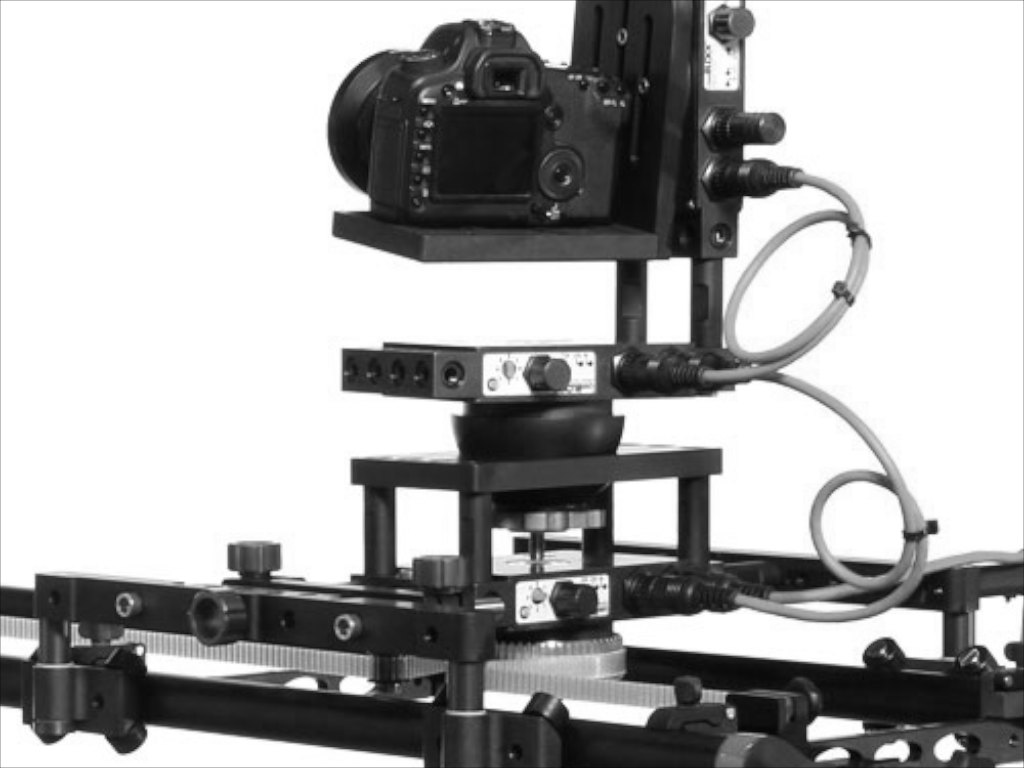
camBLOCK, one of several available camera motion-control rigs.
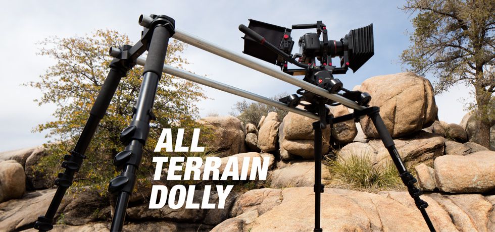
This setup from iDC is a nice outdoor system, but is passive: all motion is done by hand.
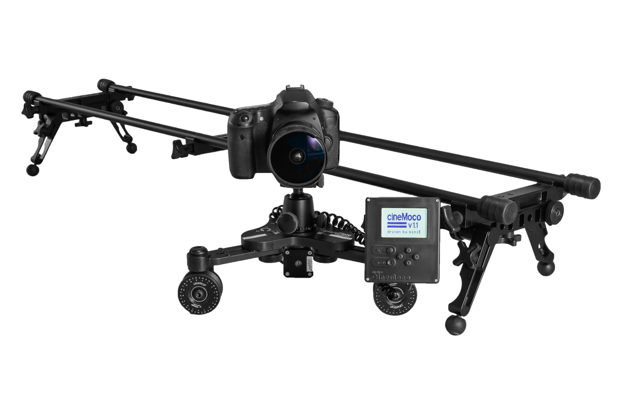
This system from cinetics is easily one of the most appealing options. It's not yet available, but it does offer linear motion control. Unfortunately it does not provide pan and tilt, and the wheel bearing system means it relies on gravity to keep the camera on the rails.
On the other end of the spectrum are more DIY-type projects. Generally, the designs don't offer the same reliable motion of the professional products or the comprehensive integration with other existing camera gear. However, some of the DIY designs can be particularly clever.
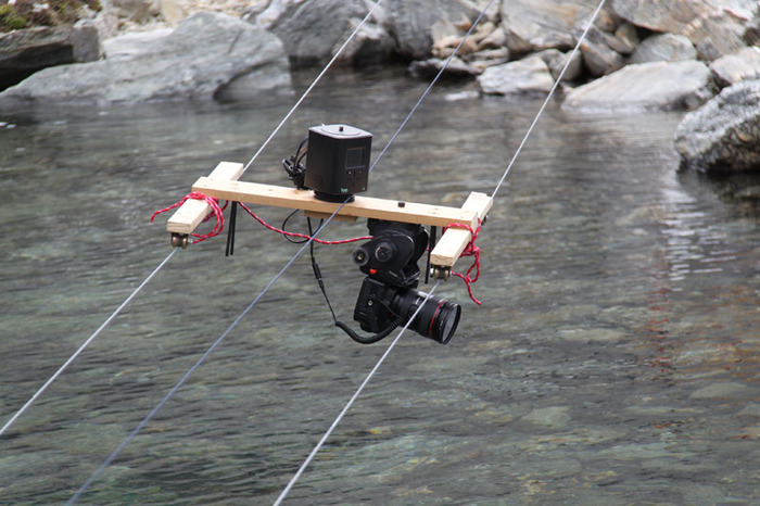
The Genie is an interesting idea. It's a complete product, but it's built in a generalized way that requires specific, DIY add-ons to create the desired motion for a specific shooting situation. Really awesome if you have the time (and trust) to build your own setups.
For the timelapsing backpacker
While both the professional-level products and the DIY projects are designed to be transported to a location and setup on site, neither set have really developed an appropriate package for the backpacker photographer. Ideally, a motion-control camera rig for the timelapsing backpacker would be lightweight, compact, and robust to handle variable and unpredictable environmental conditions.
Building Visual Models
There are still several questions about the system architecture, scale, and what components are used. Parts such as the 5/8" tent pole sections, teflon sleeves, tripod ball-head mount, and collapsing trekking poles were integrated with some quick prototyping materials in order to develop a mockup of the system. This was a really helpful visualization exercise that produced new ideas for the next iteration.
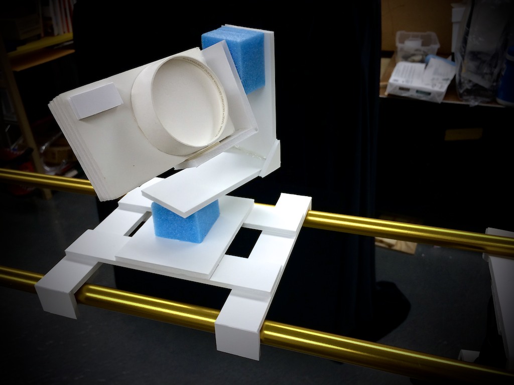
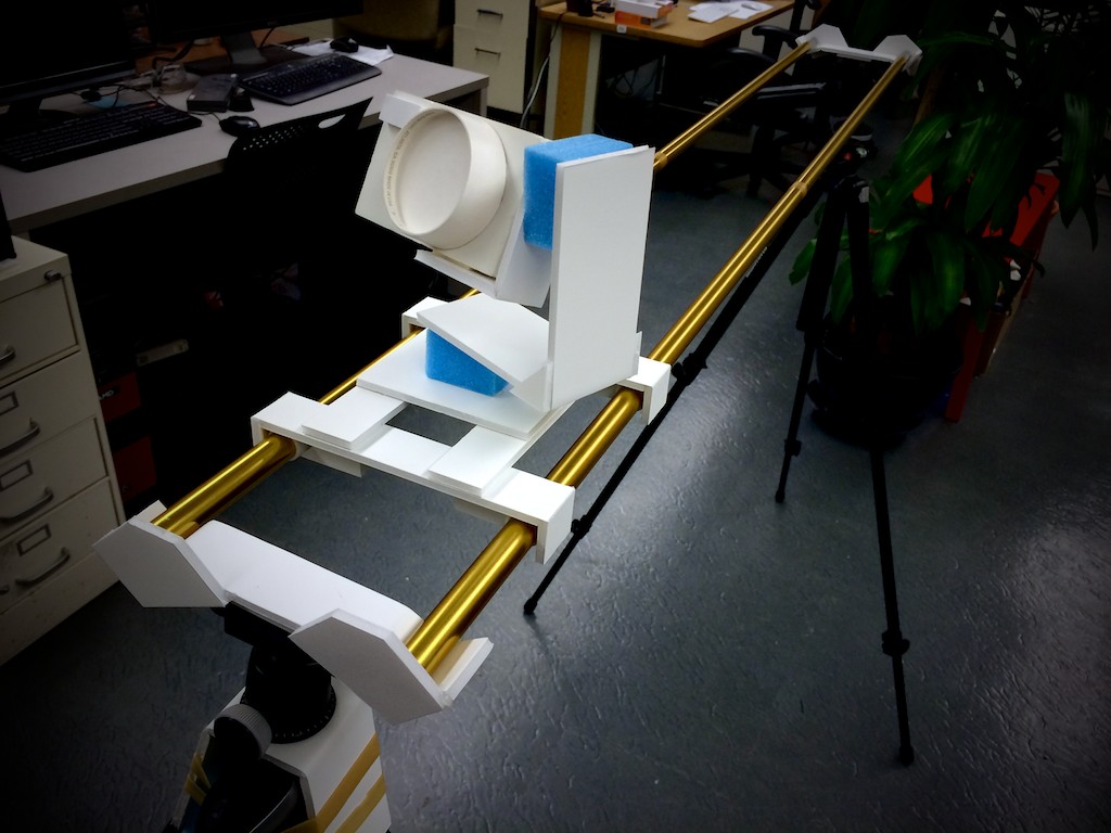
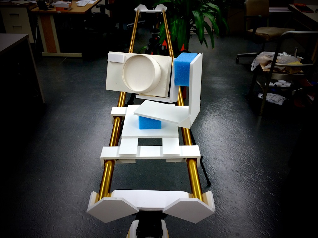
Moving along, the teflon sleeves and tent pole combination worked really well—very smooth sliding. Building the camera gimbal, it seems like there should be more compact ways of packaging this.
Changing Directions
After spending more time thinking about the design of the motion rig, I started to seriously doubt I could finish all three motion axes in time. I decided to simplify to one degree of freedom and instead make a controlled turntable for 360-degree photography.
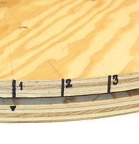
Photography turntables exist in several forms. Some of the simplest are glorified lazy Susans where indications are in marker and they are actuated by hand. Mid-range turntables have motors, but they spin at a constant rate—making it difficult to use a slower shutter speeds or battery-powered speedlights that take time to recharge. Hi-end turntables do have motor control to work better with multiple exposures, recycling speedlights, etc., but these can get quite expensive.
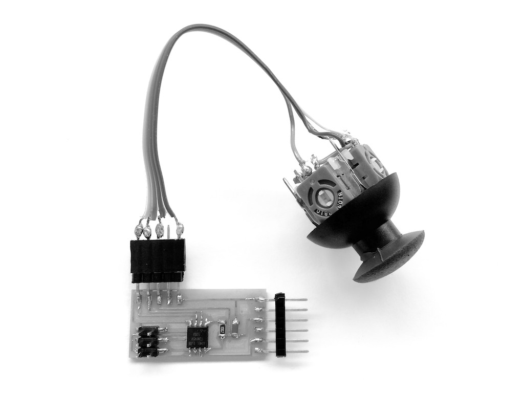
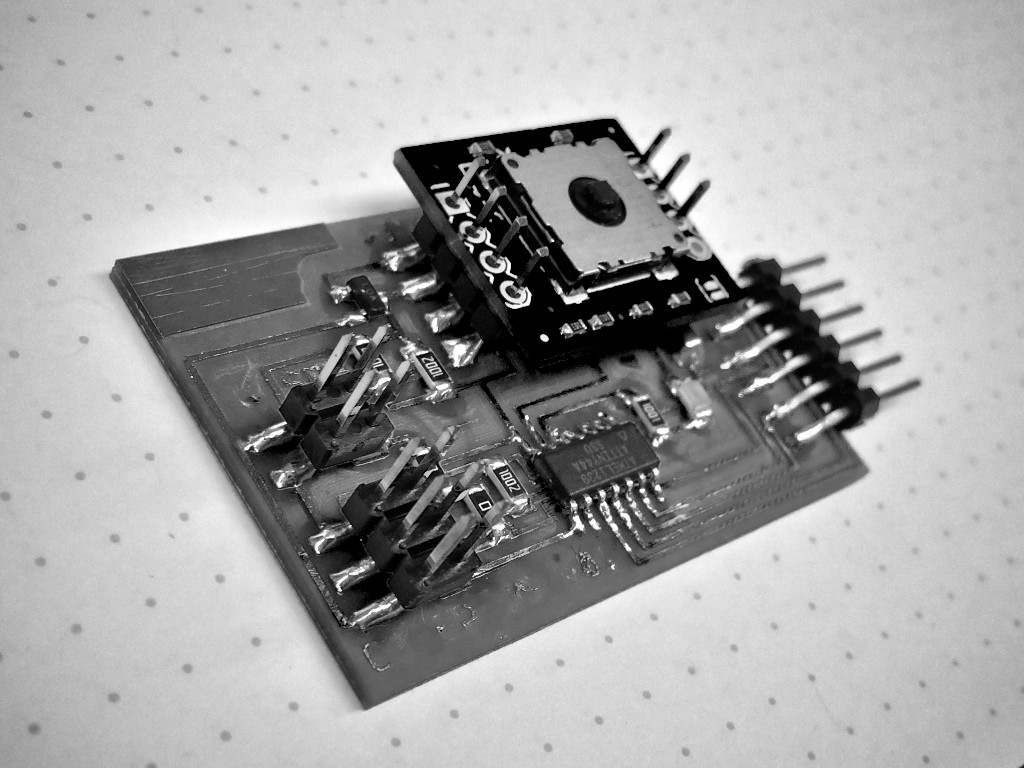
My plan with this project is to use a stepper motor to control rotation of the platform and synchronize the movement with the camera shutter. For control of the camera, I'll setup two of the pins of the micro controller to act as a remote shutter release: one pin for the focus, one pin for the shutter. I found a really helpful website for diagramming the pinout of the Canon mid-level DSLR remote shutter release.
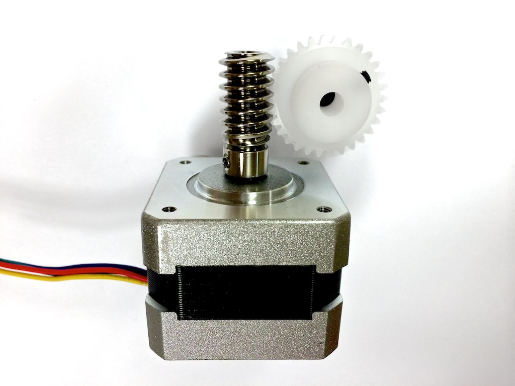
In order to be able to drive heavier objects on the platform, I bought a worm and worm gear set from SDP/SI. Originally this set would have been used in the 3-axis version, but they're now repurposed for the turntable project.
One of the challenges of using a turntable for photography is getting the right placement of the subject at the center of rotation. I want to be able to incorporate into the design a one-way clutch so the platform can be motor-driven one way but also easily spun manually the other way in order to check the subject for eccentricity.
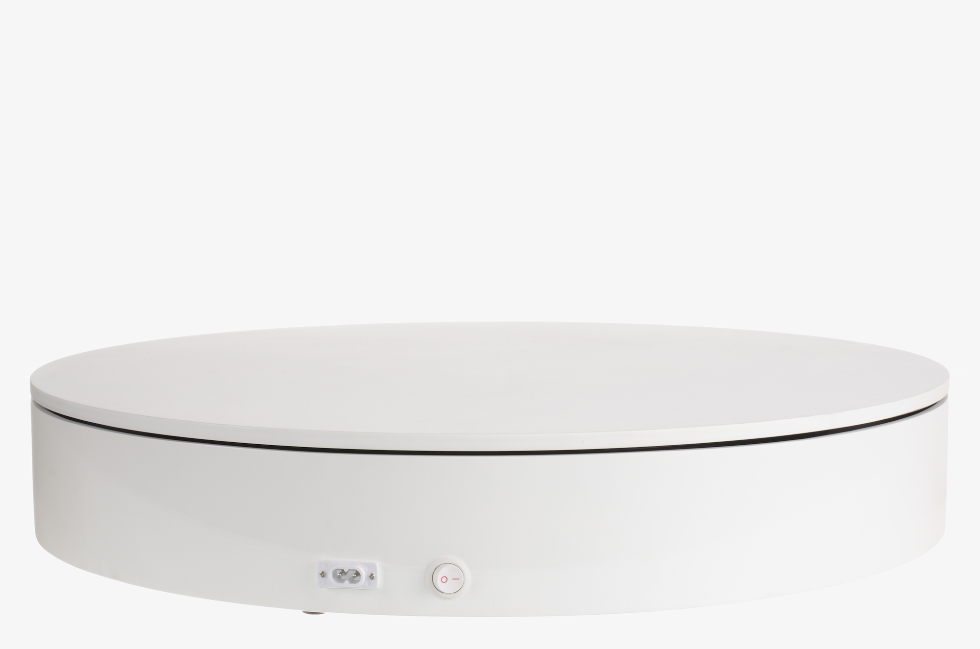
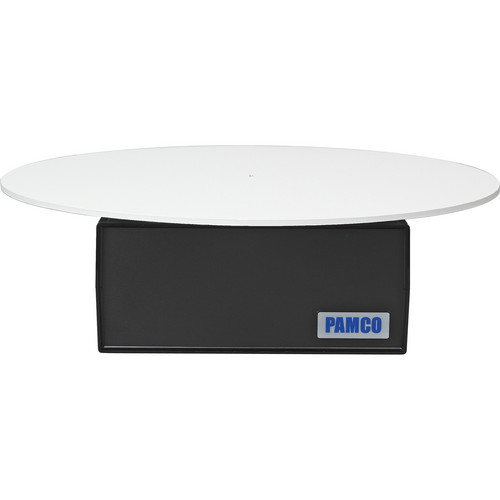
Since this new design direction, I've ordered a few helpful components such as a large-diameter turntable from McMaster-Carr. I plan to 3D print a collet for the drive shaft to make it easy to swap in different platform sizes and materials (flat, translucent, or mirrored), and the majority of the frame and mounting surfaces will be laser cut.
Building the Prototype
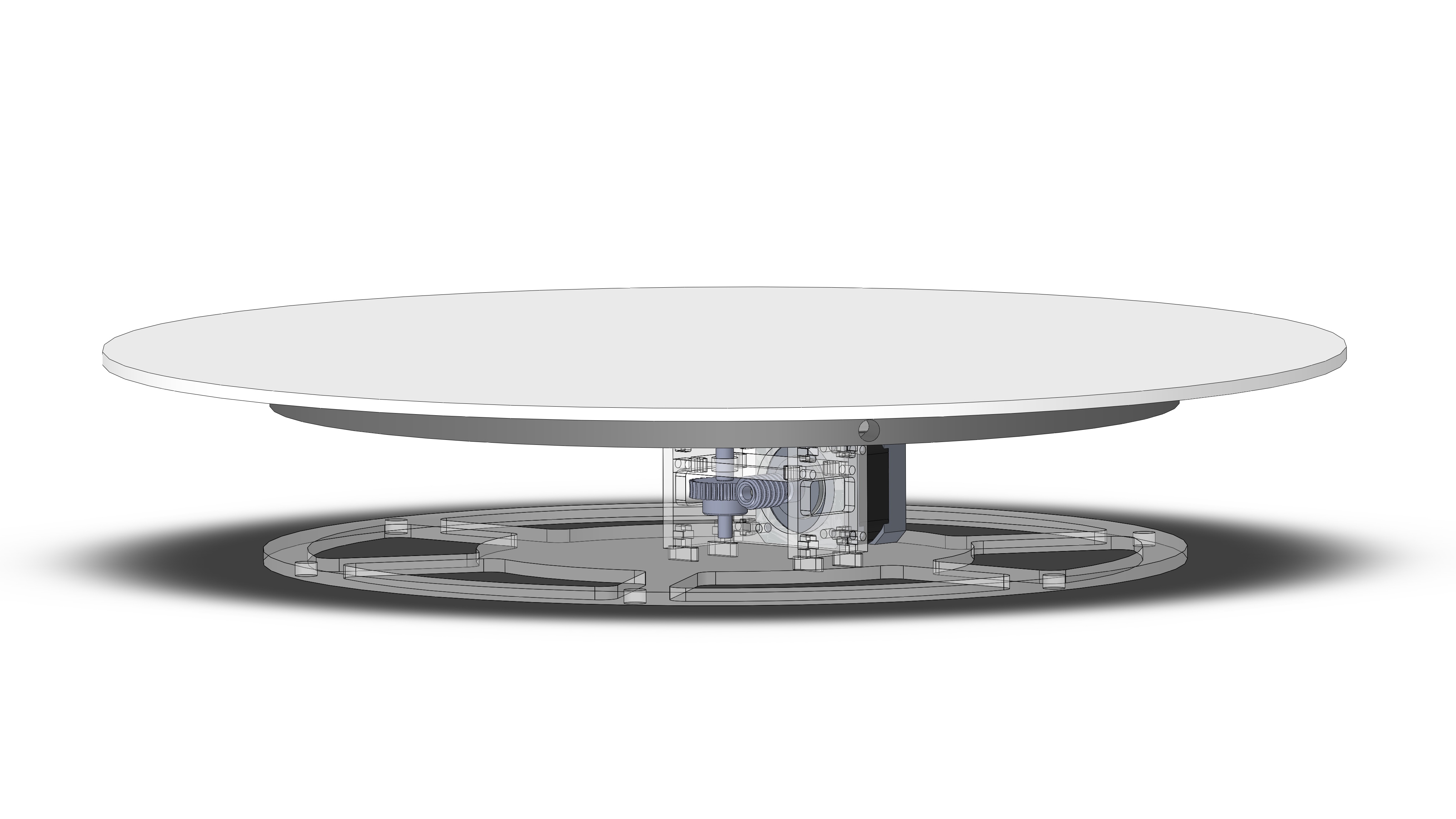
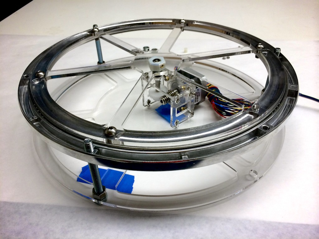
While I waited for the one-way clutch, turntable, and a few other parts to arrive, I started to do more detailed design in SolidWorks. The form would be wide a flat in order to remain stable while supporting different products. While the turntable bearing would come to define the overall area, this left plenty of volume underneath for the movement and electronics. In this design, I also started experimenting with the design for removable photography platforms (different sizes and materials).
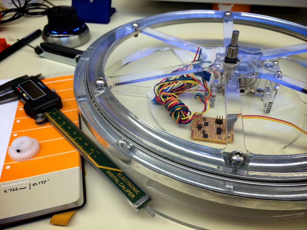
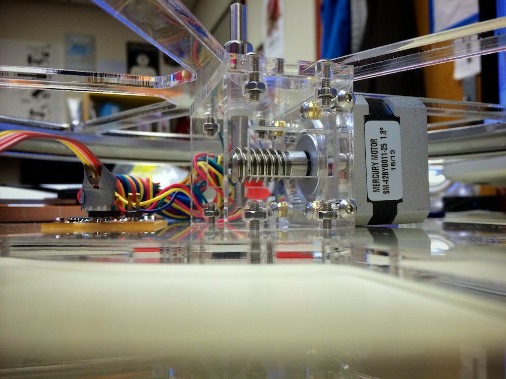
Once the parts arrived, the CAD was far enough along that I could begin using the laser cutter to make some of the acrylic parts. Partly because the stepper motor already used M3 fasteners, I decided to standardize the rest of the design around M3 features. I used a T-slot construction method with M3 nuts and bolts on the 4.75mm-thick acrylic. Although there was an upfront cost for designing the geometry of the connectors, in the end I think it made construction and adjustment much easier (and less messy) than using adhesive.
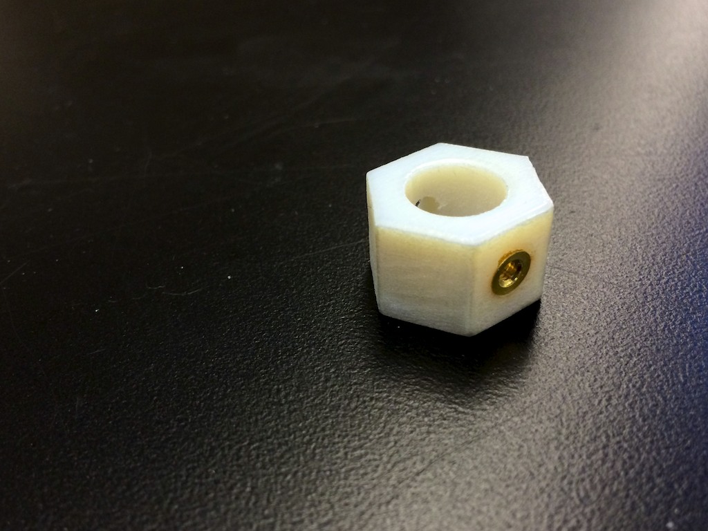
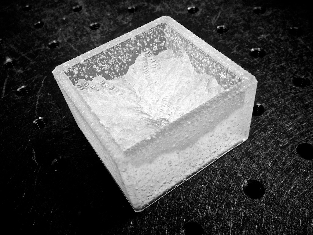
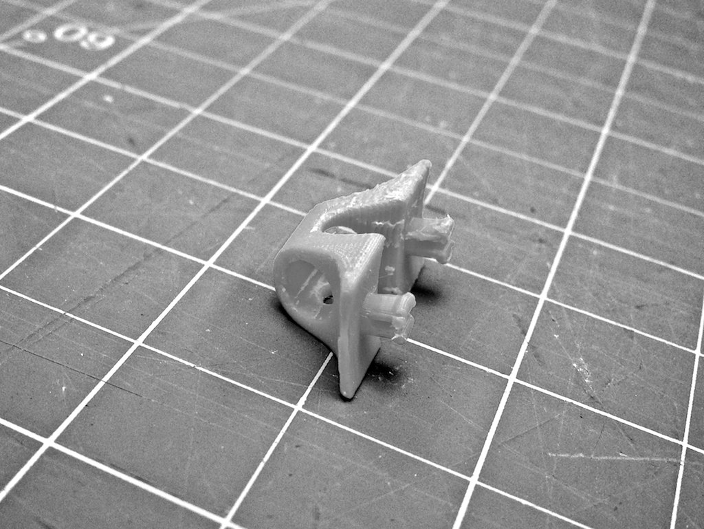
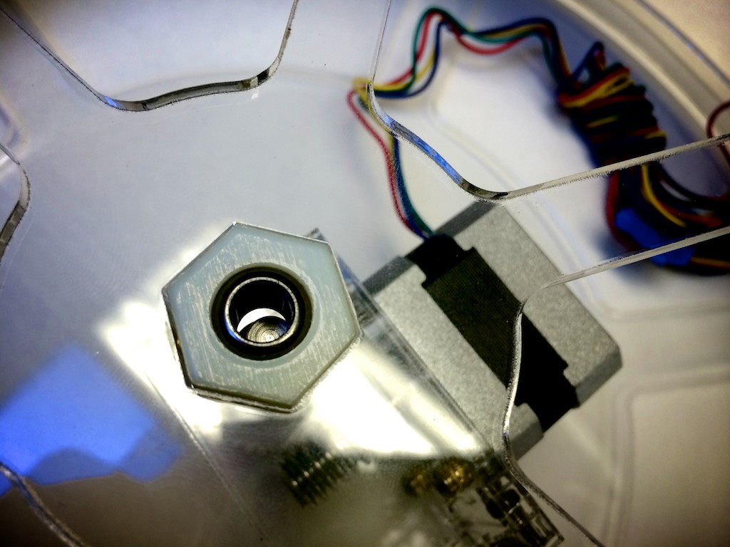
One part I had fun with was this hex collar that connects the one-way clutch on the driveshaft to the inner ring of the turntable. This part didn't need to be 3D printed—in fact I designed it around a standard size—but I was really excited to experiment with M3 threaded inserts. The part printed with slightly under-sized holes, and then I used a soldering iron to heat the inserts as they were pressed into the softened plastic. Pretty neat.
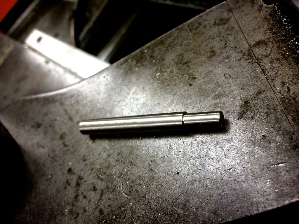
Unfortunately I couldn't stay in metric with all the drivetrain parts—mostly because I wasn't able to get the metric nylon sleeves and one-way clutch in the sizes I wanted. Therefore, it was necessary to make a step in the driveshaft between 5mm (the worm and worm gear ID) and 1/4" (nylon sleeves, lock collar, one-way clutch). The lathe makes such beautiful parts, and it only took a few minutes to make this stainless steel shaft at the Edgerton Student Shop.
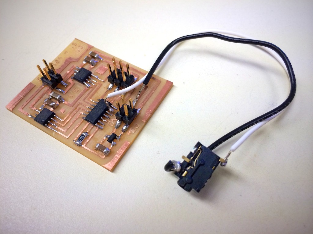
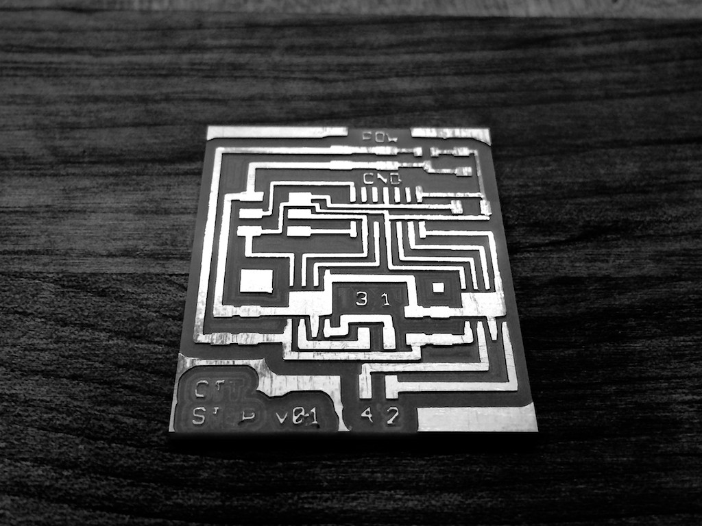
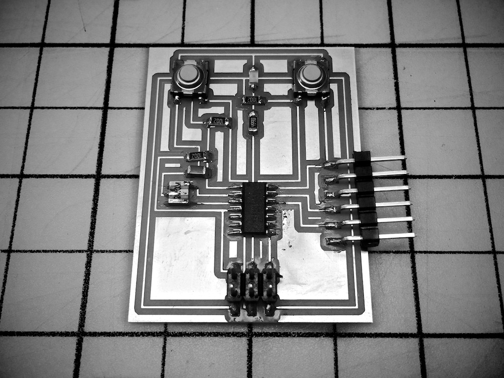
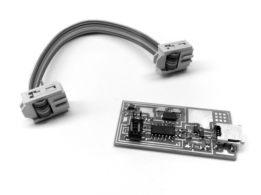
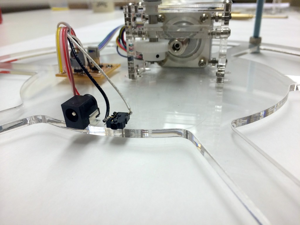
Concerned about the time involved in making an entirely new board, I modified an earlier board I had made to incorporate a 2.5mm jack for connecting to my Canon DSLR's remote port. (Most Canon Rebels, as well as the 60D, use a 2.5mm connector for the remote port.).
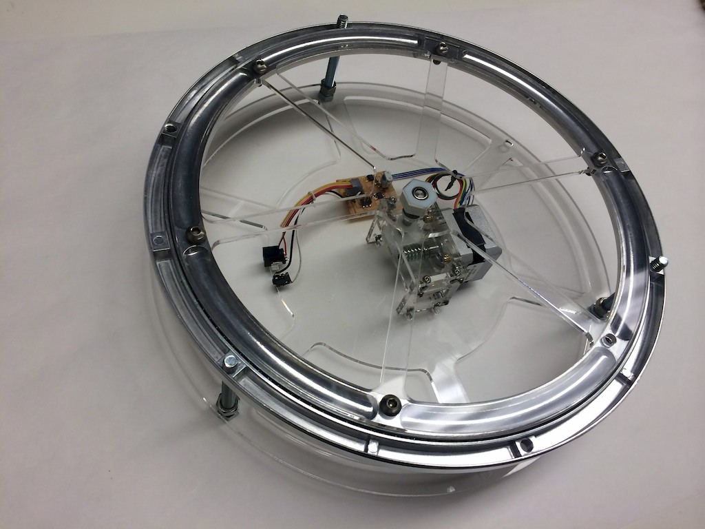
Assembling the parts together went by without a hitch, except there seemed to be a slight mismatch in location between the turntable's center and the driveshaft coming up from below. There was some adjustability in the T-slot connectors, but not enough to account for the mismatch. Considering everything in the assembly worked in CAD, my guess is that there was some eccentricity to the cast parts of the turntable bearing. After all, I don't think it was intended for precision use. The solution was a relatively easy fix and involved re-cutting the bottom plate with slotted mount points for the motor-drivetrain assembly.
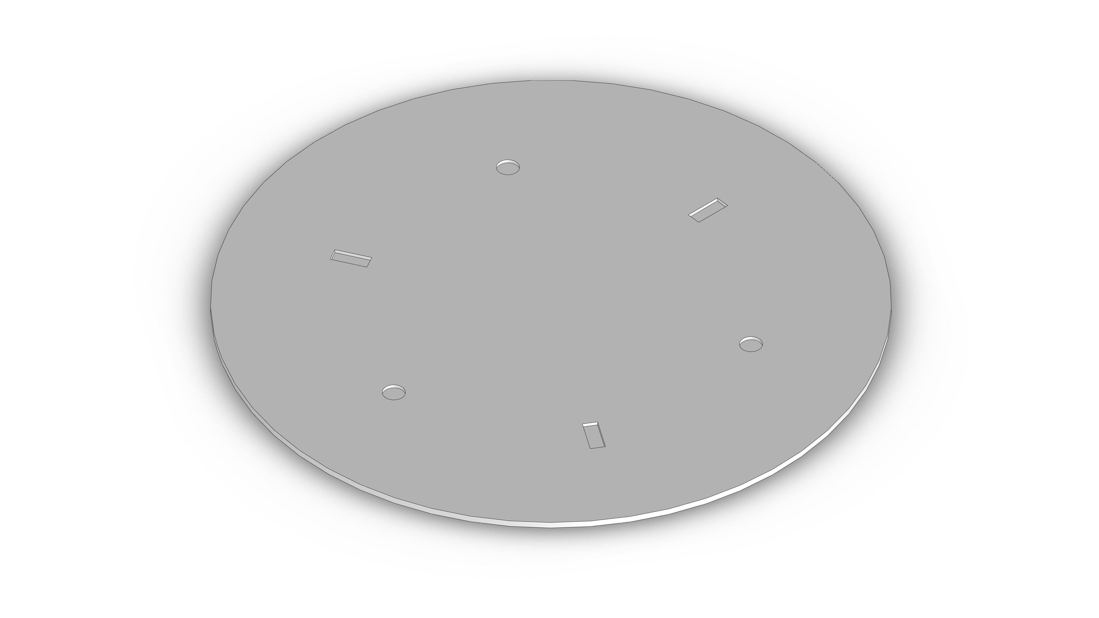
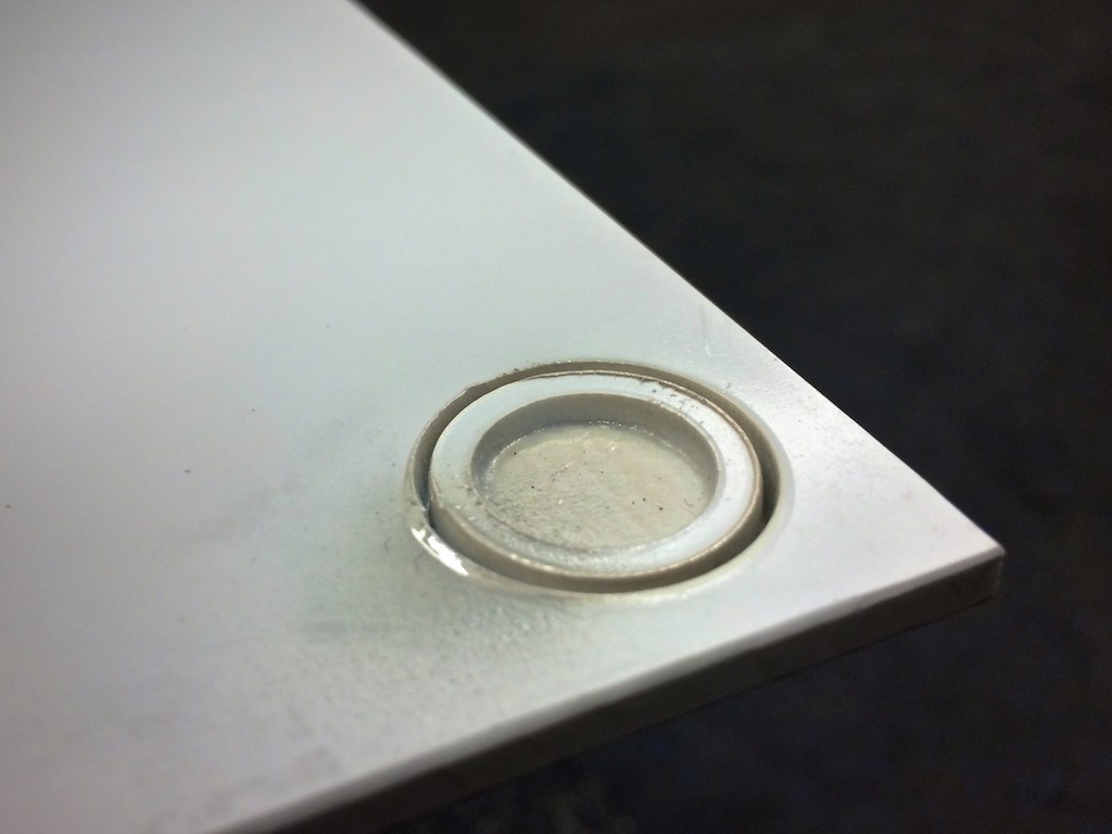
Next, my attention moved towards the removable photography platform. Envisioning that I would later experiment with different materials and sizes for the platform, I wanted work on the platform to be relatively simple. Ideally, only a few operations would be necessary to turn a piece of stock material into something that could mount effectively to my turntable base. Remembering the example in lecture that we had seen of a type of kinematic coupling led my inspiration for how the platform would interface with the base. Given that I already had a 6-bolt pattern, I could use three of the bolts paired with three channels cut into the platform as a kinematic constraint. The platform would automatically become centered and rotate with the base. Technically the other three bolts would over-define the geometry, but since the relatively thing platform wouldn't be perfectly stiff, I decided to cut slightly deeper, oversized circular features in the platform to match up with these last three bolts. The purpose would be that any flop in the platform that would result in an unacceptably wavy surface would instead be supported at these locations.
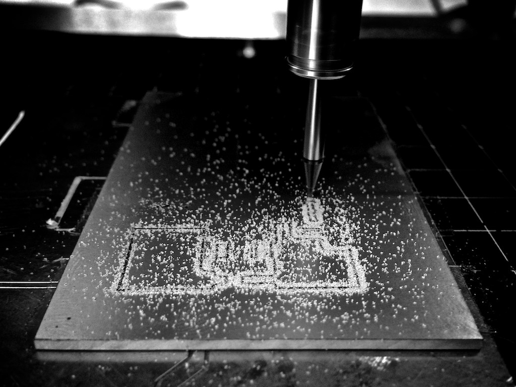
In order to achieve these different slot and circular features, I used some of my scrap ABS on the laser cutter to experiment with doing rasterized depth cuts. The depth cuts didn't nearly go deep enough at first, but I slowed the speed down until I could cut as deep as 0.08". However, this proved problematic because the heat created in the process produced an off-color area on the opposite side of where the ABS had been rastered (the top photography surface). Speeding the raster up to 12% eliminated the yellowing, while still producing an acceptable cut depth. On the 60W Universal laser I was using, this resulted in 100% Power, 12% Speed, and 500 PPI for a raster depth of about 0.07".
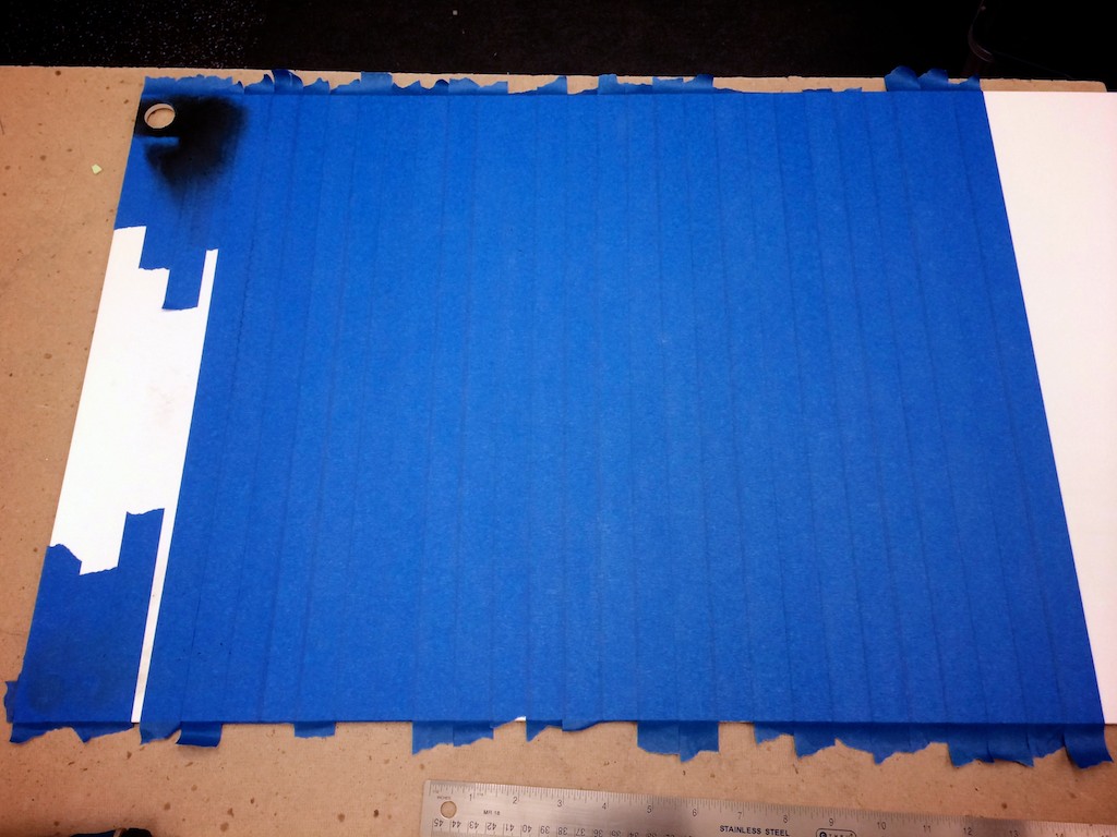
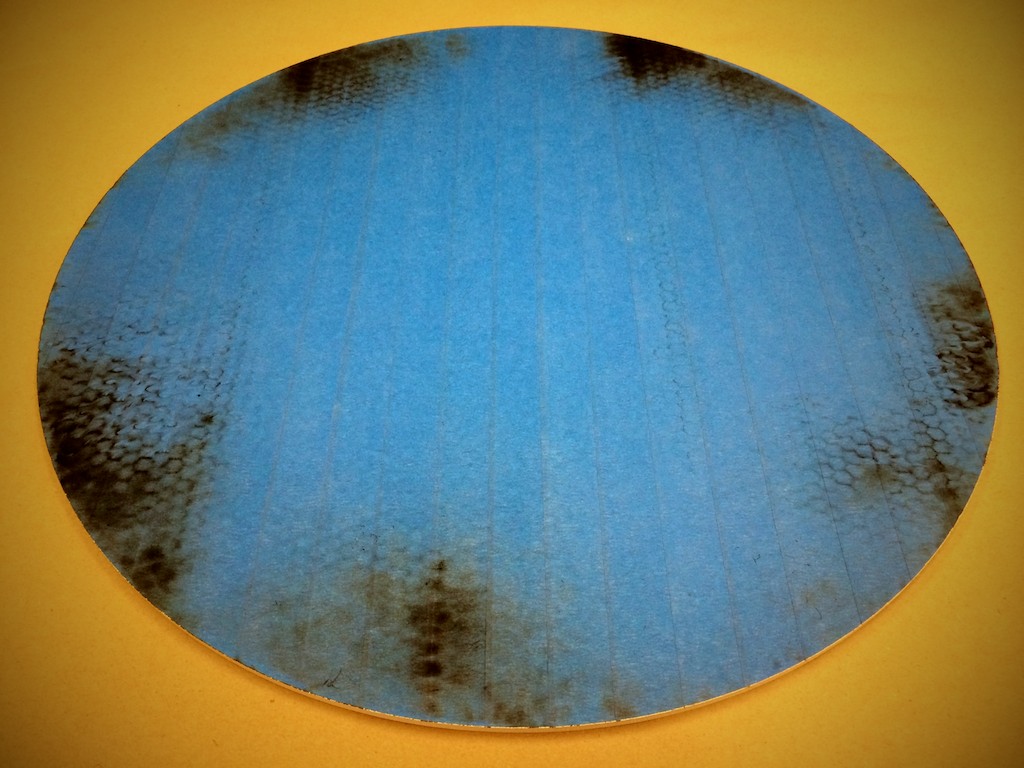
Learning from past experience, I covered the underside of the ABS sheet in tape during the cutting process. This would eventually become the top photography surface and it was much easier to keep clean this way. At the end of the cutting, though, it did produce a sort of nice-looking burned blue disc.
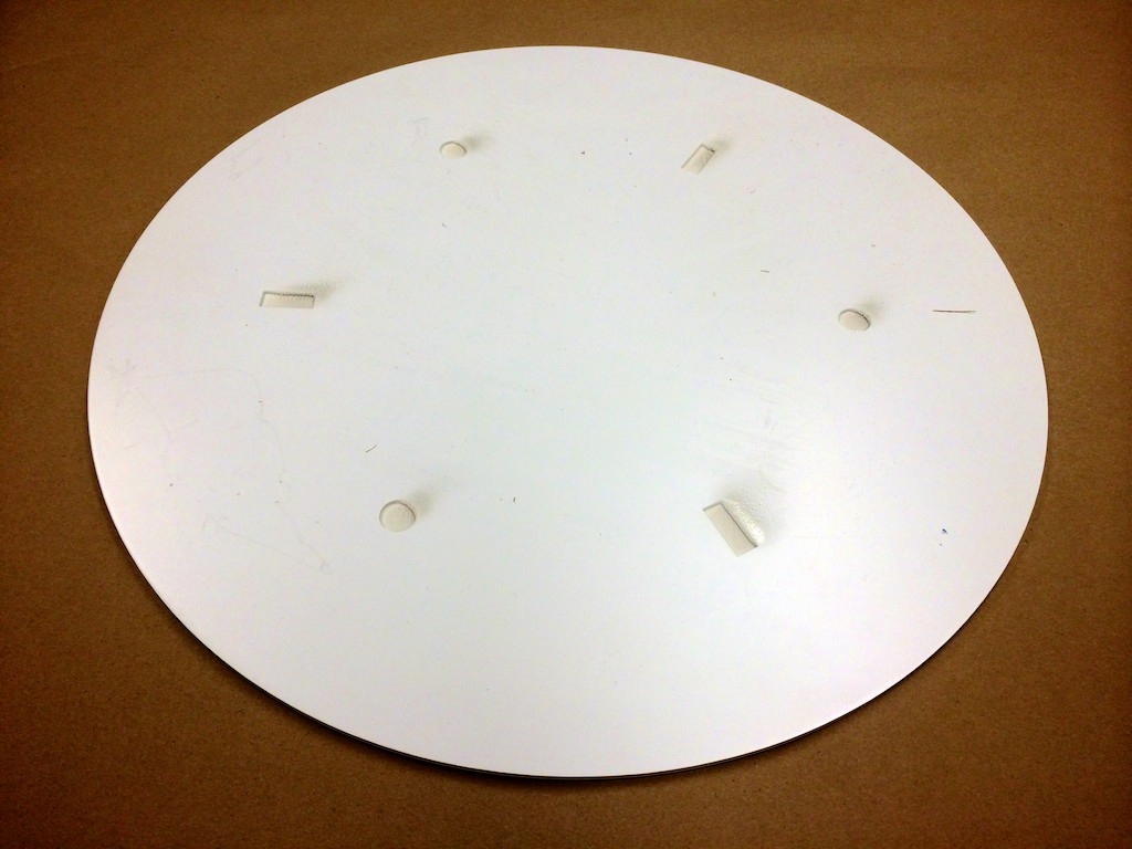
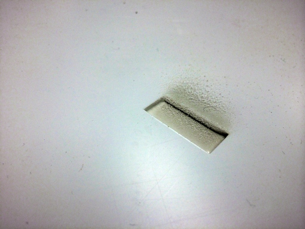
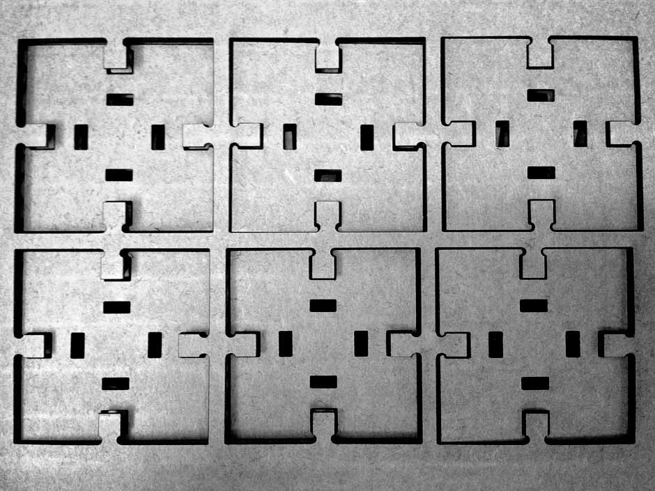
This is how the raster depth-cut features came out of the laser cutter. There were a lot of plastic flecks deposited on the surface from the cutting process, but these separated pretty easily with a knife and a cleaning cloth. Although the bottom surface of the cuts were a little rough—definitely a visible linear artifact from the raster process—it didn't matter as much as the nicely-defined edges which are necessarily for geometric constraint.
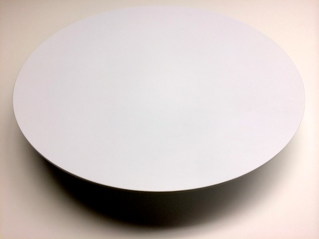
With the platform mounted to the base, the whole thing just looks like a floating disc!
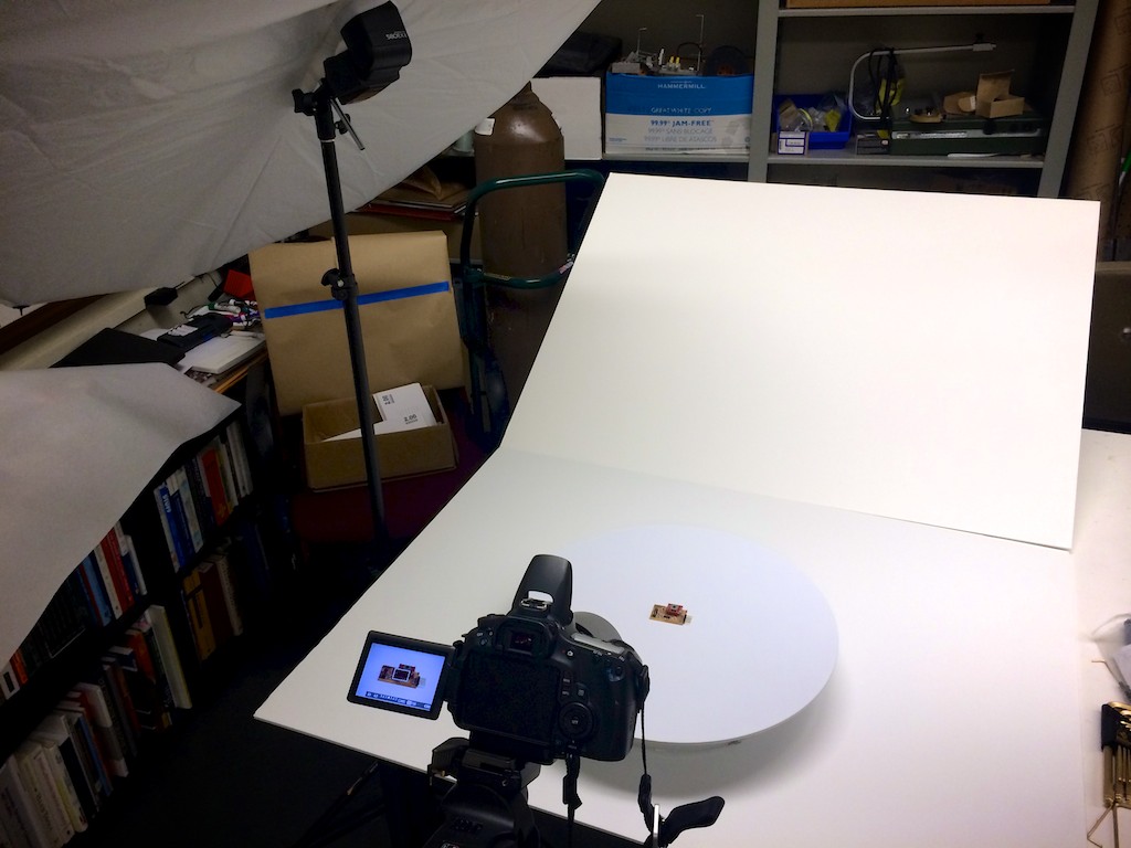
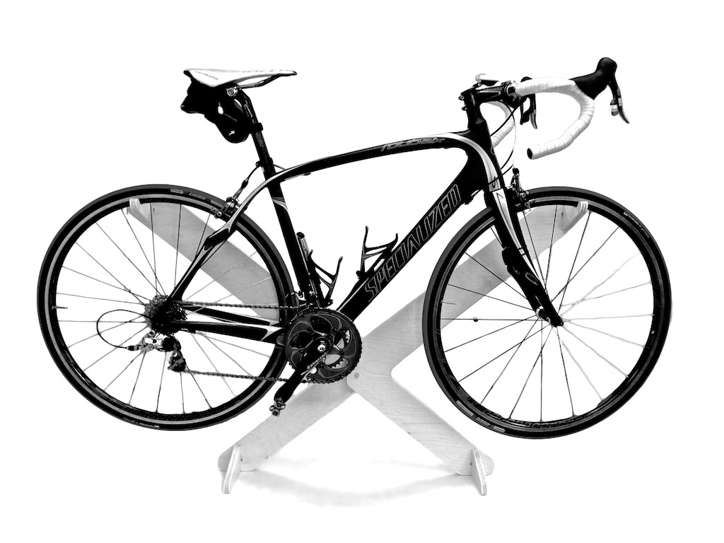
Setting up some flashes and connecting my camera, I'm ready to start doing 360-degree photographs of my projects from How to Make (almost) Anything.
A sample of the photos made with the turntable. Currently, I can create a movie using each photo as an individual frame, but it will be nice to use javascript to create a more interactive web view that can be controlled by the user.
Project Files