Designing Circuits
I forgot all of my E&M the moment I decided to write code for a livingThe project this week was to design a circuit that "did something", namely, light an LED when a button was pressed, based on some programming to be done in a later unit. I opted for the basic "add a button and an LED (and a resistor with it) because I'm a code monkey, not a circuits person.
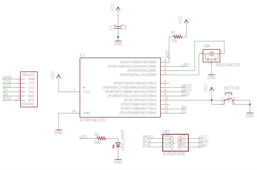
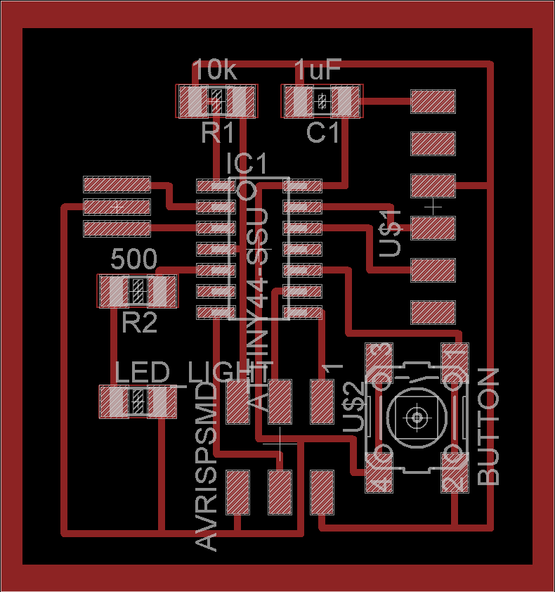
I built the above circuit schematic, which describes all the parts of my circuit and how they're interconnected, using the semi-free Eagle software with parts from the fab partslist sent out by the professor. The best thing about it is that it doesn't look like a snarled mess of circuitry, due to Eagle's ability to label wires with names that allow them to be implicitly connected, even when the parts look separated. Also, Eagle lets you separate the circuit schematic from the design of the board itself, which I ended up building two versions of.
This is my first version of the board; it had a lot more space between wires and components because I was leery of soldering in too small a space.
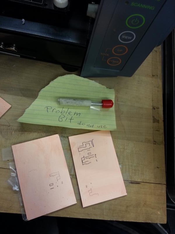
Unfortunately, this iteration of the board ran into two major snags, one inexplicable and one slightly less so. The first came after I tried milling the board for the first time, realized that the drill bit was too dull, and tried to swap it out for a sharper bit.
seriously this is terrible
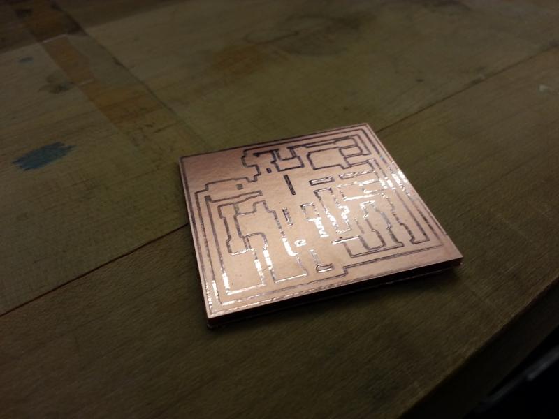
But for some reason, the 1/64in bit I replaced *refused* to cut deeper into the surface of the PCB and kept making pretty-and-clean-and-useless patterns on the copper. I checked almost everything; the tightness of the screws on the head of the modela, the bit's sharpness (it was pretty sharp), the cut depth (I set the cut depth to .2 in desperation, which would have been kind of suicidal if it had worked... but nope), even the list of jobs in linux (thinking that one of them might have been screwing up the current job). However, the replacement 1/64in bit simply refused to cut. I even cut out the following board with the 1/32in bit to make sure the modela wasn't just breaking down, and the below image shows how pristine of a job *that* did.
I don't even know
Finally I gave up and waited for Charles to just replace the bit, because we were out of 1/64in bits at that time.
shame on you, shame on your family, shame on your cow
Anyway.
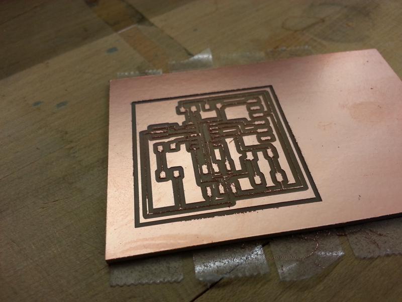
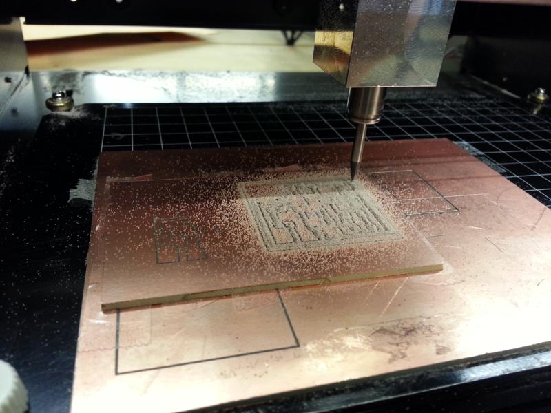
The second snag came when I came back and actually managed to mill out the board's wires with a functional 1/64in bit. Look at it run!
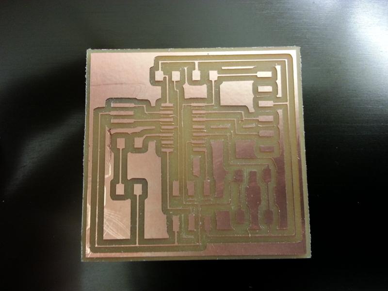
But those wires are way too thin and flimsy for any long-term circuit usage!
Unfortunately, due to my previous exasperation with the non-cutting bit, I ended up setting the cut depth too low - to .125 instead of the recommended .11. I believe that's what caused the drill to mill out more than it should have (it's conical; milling deeper meant the thicker part of the drill was cutting out more stuff), and made the wires in this board so thin. I also realized (with some help from Mohit) that I could set the grid settings in Eagle to .125in per square, instead of the .5in I had somehow made do with in the previous board design.
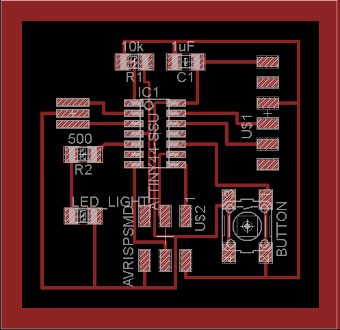
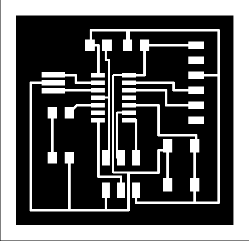
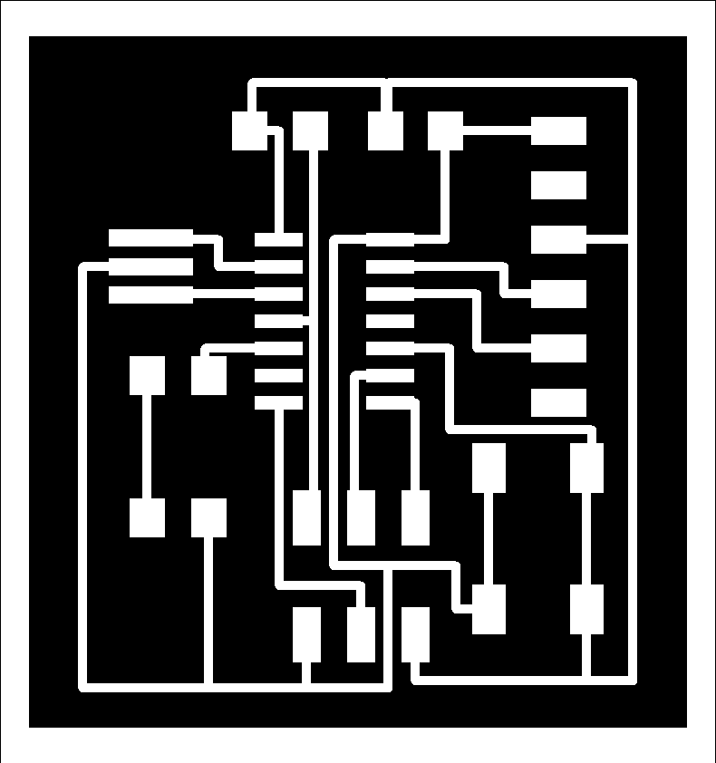
So before I cut out another board, I went and restructured my circuit drawing, making it more space-efficient but with thicker wires, and putting more distance between wires. The below is the final board design I went with.
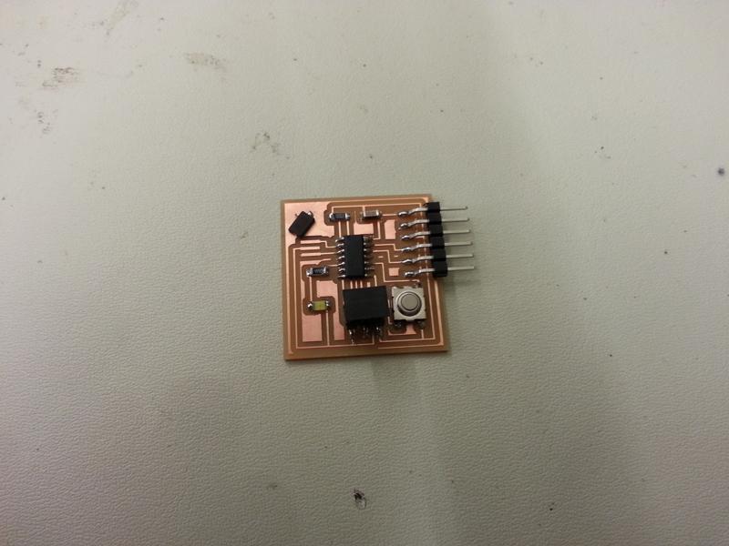
Happily, this board both cut as intended and had nice wiring, so I soldered it. Unfortunately, during soldering of components onto the board, I realized the IDC lab didn't actually have the three-bar resonator/crystals called for in the initial echo_hello diagram, only two-bar crystals which didn't fit. I ended up soldering a crystal to an unused part of the board as a reminder to myself that I need to either get that three-bar resonator, or redesign the board to use the two-bar crystals instead.
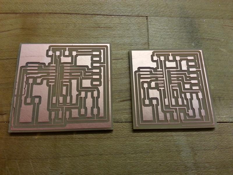
Comparison between the initial board and the final board