Input Devices
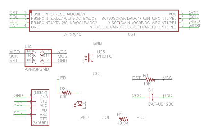
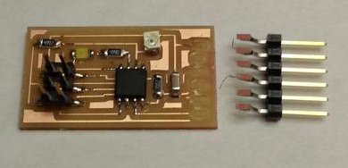
There is no greater threat to board integrity than a sleep-deprived grad studentI decided to make a photosensor board this time around because I figured it would be both easily testable (without too many strange looks from other people) and reasonably simple to program. My original design for the board started from Neil's provided hello.light.45, but I saw that the attiny45 had an extra pin, and decided to add a resistor and an LED to it, so that I could program the light to go on when the sensor went dark and off otherwise.
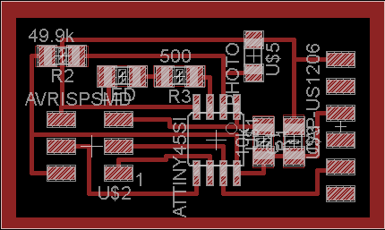
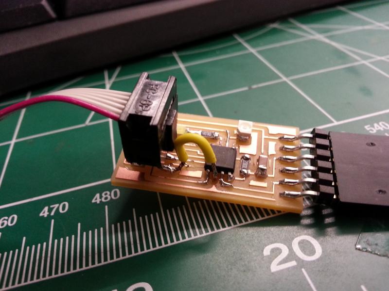
Unfortunately, this board design ran into a few interesting snags off the bat. The first was that - and I didn't even know you could do this - while I was trying to power the board with the 6-pin connector, the header got stuck, and when I pushed a little too hard on it I managed to rip the entire header off the board along with its six traces. (Tip: wiggle the connector from side to side and *slide* it onto the header)
Thankfully I'd milled a second board beforehand in expectation of something like this happening - but it turned out two boards wasn't enough; the second board ran into two issues. The first was that, by keeping the soldering iron too hot (~400C) while trying to solder the attiny45 to its (tiny) traces, I managed to burn a trace straight off the board. I ended up attaching a wire to connect the pins that that trace would have linked, but it might not have been adequate:
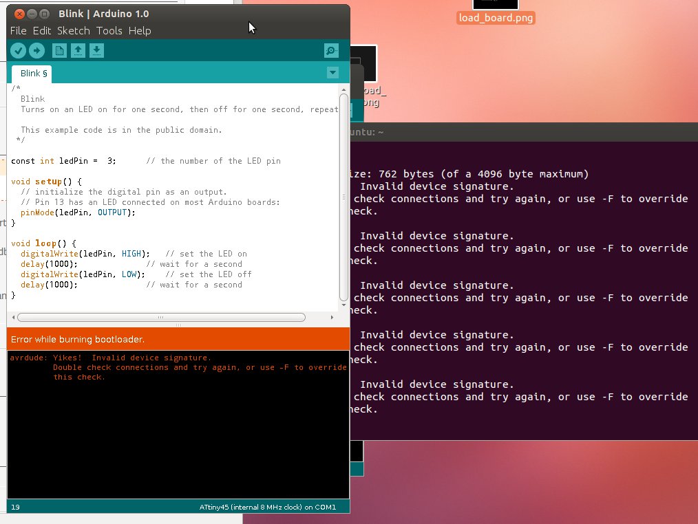
1. When I tried to program the board with the IDC lab's AVRISPII and the arduino UI, although the AVRISPII lit up nicely when the board was powered and plugged in, the system refused to recognize my board and burn the bootloader. Because the board had already had a wire tacked onto it, I couldn't be sure whether it was my board design that was faulty or my attempted fix.
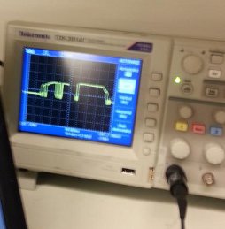
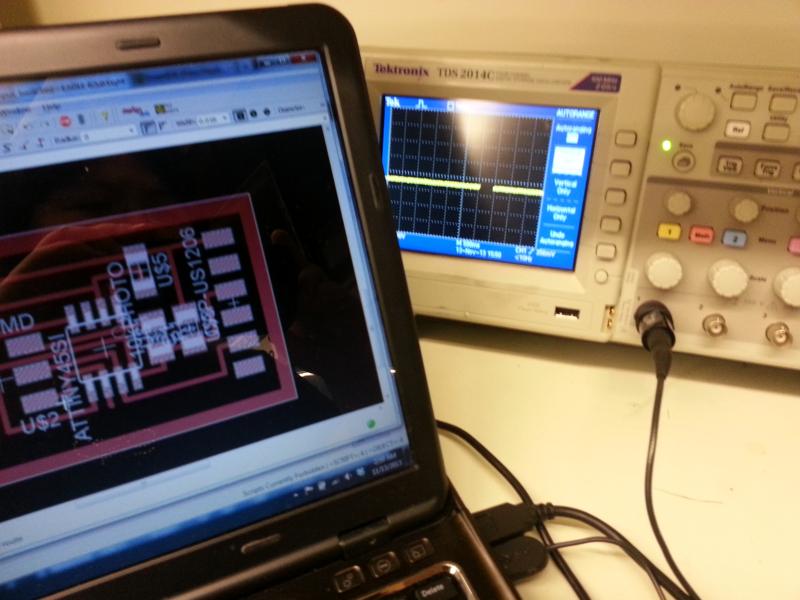
2. I then took the board to the oscilloscope, to see if I could at least measure a noticeable change in voltage across the photoresistor. Unfortunately, I couldn't detect anything there either, leading me to believe it was my board design that was fundamentally flawed.
Having been unable to program the board earlier, I ultimately decided to give up on that for now and go back to the basics, in order to make sure I understood what the phototransistor's output looked like. I removed my added LED and made a second board design - and then a third, after I'd milled the board, soldered everything onto it, took it to the oscilloscope and got no response, and then realized that my second design was missing an important wire connection between R2 and the collector side of the phototransistor.
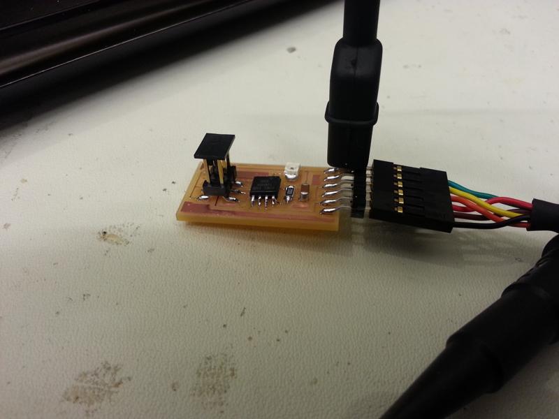
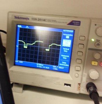
v3: Success!
I attached the v3 board design to the oscilloscope and measured the voltage across the photosensor while covering it and exposing it to light. I found that voltage was *high* when the sensor was fully covered, decreased slightly when some light was let in, and past a certain level of light, dropped to 0. This suggested that my initial idea would have been fine - having an LED turn on when the photosensor pin was high, and off when low. For next week's assignment I may implement something of the sort - or I might try using a microphone and measuring musical tones, in preparation for my final project.