

This week we are tasked with ouputting something. We are assigned with the task of designing a microcontroller board that uses output devices.
Some ideas for this week are
I read once that the key to a long and happy life is unfinished projects. At this rate I'll live to be two hundred and forty.

Be on the lookout for broken traces.

My schematic in Eagle

My components in board view in Eagle
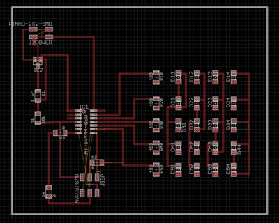
My wired board in Eagle
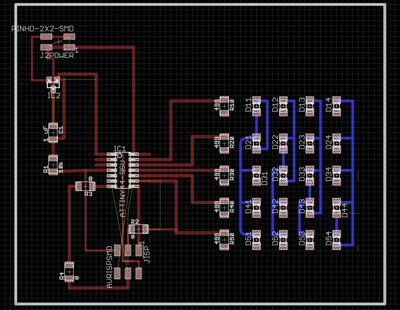
I learned to add wires and outlines on different layers


The top layer in Eagle and exported for design

The bottom layer

The vias
This week I used Neil's example to design the charlieplexing 2 sided board in eagle. This took a very long time. I knew I wanted to vinyl cut everything so I beefed up the traces and tried to avoid traces running under the microcontroller or too close together. I learned how to add items on different layers in Eagle- First click on the layer then click on the wire. I learned how to change my font in eagle and how to add a board cutout outline in the documentation layer (51) that you can export and use as your board cutout outline. I don't yet know how to get components on a separate layer but will Google this and post results soon.
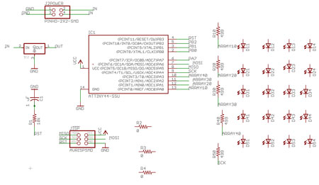
Added additional solder jumpers (0 Ohm resistors) so I wouldn't need to run as many traces under the microcontroller.
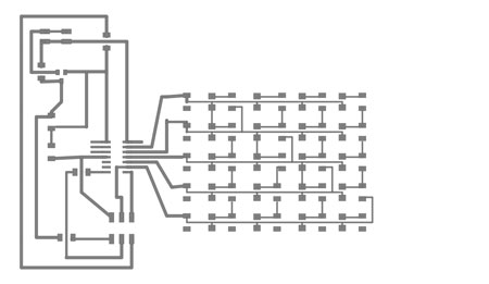
I talked to our TA Rob and he said it would be easier to start with a 1 sided board so I also designed a one sided boad using Neil's templates. This also took a very long time.
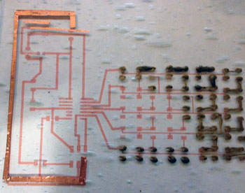
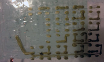
I also experimented a bit with painting traces and researched conductive fabric and paint for future projects.
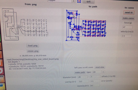
Loaded up my png in fab modules and adjusted the settings slightly. A force of 47 and a speed of 2.5 with a pen force on the machine dialed at .5 worked well. I also adjusted the tool diameter to a lower setting to get traces spaced farther apart.
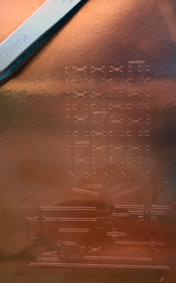
Neil said every year peole fall in love with the vinyl cutter and do everything on it. I've been trying to fall in love but it's been very difficult. This week the vinyl cutter and I had a very good 4th date. Not sure if it is true love yet but it is definitely promising. I decided to try vinyl cutting the board again because I am a glutton for punishment. I adjusted the pen force, speed and the depth pen was sticking out of the vinyl cutter. I began to cut and things appeared to be working well. When designing my board I didn't design any traces under the micrcontroller because this is where things were ripping before. I also increased my traces to 36 mills where I could and spaced components fairly far apart. I also changed the tool diameter size in the fab modules to be less than the standard setting so the traces would be even wider when they cut out.
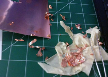
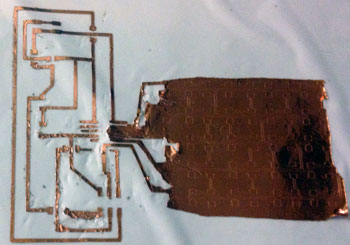
This took a really really long time. NOte if this step is really painful and taking too long your traces may be too thin.. OR your vinyl cutter may not have actually cut all of the way through- If this is the case you are better off cutting again and starting over. I cut out some pads and traces and used previous boards to repair broken traces on the final board after it was weeded.
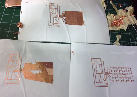
It is easier to weed if your cutter has actually cut all of the way through
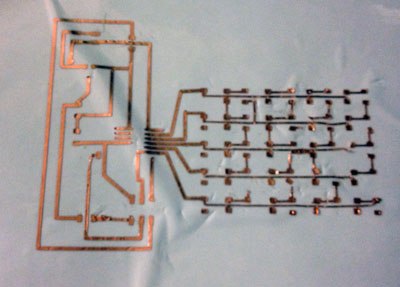
A few of the traces ripped up and were lost in the wedding process so I used the cut vias to replace pads and traces from previously cut boards to patch and repair the final board.
I gathered my parts and placed them on the double sided sticky tape with a label.
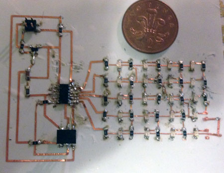
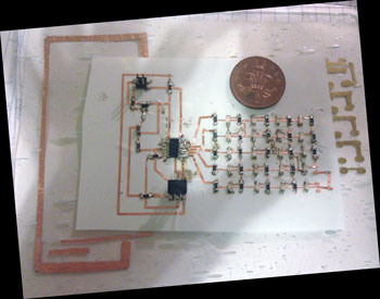
I wanted to use lead free solder for my circuit so I found some lead free solder in the bin, turned my soldering up to 825 and soldered away. It was not much worse than regular solder! This part was a bit tricky with the vinyl cut traces. I guess the adhesive on the copper is really sensitive to heat so whenever I'd heat the traces to solder them they'd move and squirm around. This was very frustrating. Also flooding a component with solder and then sooaking it up with the copper braid didn't work well AT ALL because the traces moved all around when I was soaking things up and melded together. The connections to my microcontroller look very messy and hideous. Also the plastic substrate I'd mounted the traces on melted so I ended up affixing it to a piece of glass. Next time I'd use a different substrate or just weed directly onto the glass. I ran out of lead free solder with only three 0 ohm resistors left to solder. Very disappointing. Really want to finish this soon to test it out.
Coming soon
Stay Tuned
Coming soon

Coming soon


Copyright 2013 Kathy Sinclair