The assignment is to create the FabISP for future use in the class. The circuit board needs to be milled using the Modela. All components need to be located and placed on the board and the board needs to be programmed so it can program future circuits.
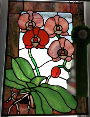
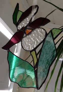
This week we are making a circuit board! How fun is that! I get to work with lead, copper, machines and scorching heat! I created a few stained glass panels many years ago and this was my only previous experience soldering. So I thought, how hard can soldering a circuit board be? It is much much smaller. Not quite the same.
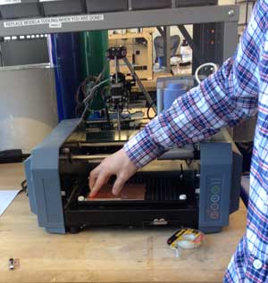
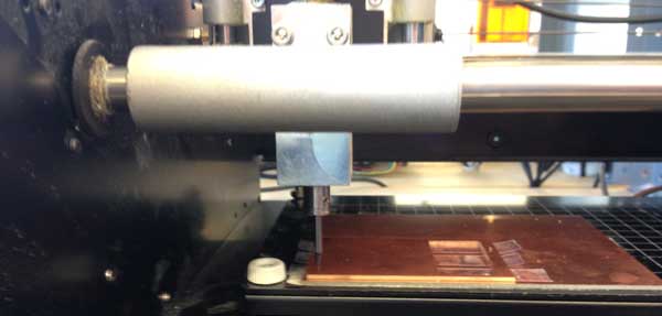
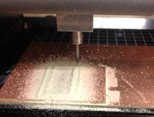
I started the fab modules and loaded Neil's FabISP traces. I then changed the endmill to the 1/64th bit. Then changed the xmin ymin position to line up to the origin. When I found a good position I marked the settings for xmin and ymin in my notebook and started milling.
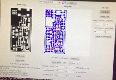
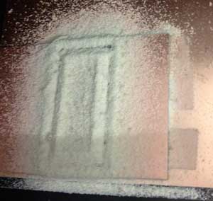
When I milled the interior traces on the Modela one half of the board was being cut into and the other half was just being polished by the 1/64th endmill. So we removed the sacrifial layer of copper and placed a new layer down to ensure that the surface that my board was mounted on was level. This did not work so we tried a brand new bit. This did not work so we rezeroed the machine and tried again. We then changed the cut depth to -.2 and changed back to the old endmill and the traces were successfully cut out! If at first you don't succeed try, try again? And again? And again!
I first milled the traces and then cutout the board. I remembered all steps exept to change the setttings in the fab module to cut out board. This is Important and needs to be done!
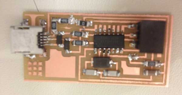
Need to remember to change the settings in the fab module to cut out board, change your end mill to 1/32nd, tighten your end mill and change your number of offsets from 1 to 3. My end mill was already broken before I inserted it. I did not check this. So be sure to Check to see if your endmill is already broken before placing it. I forgot to change settings in the fab module to cut out the board and got so excited and removed the board only to realize my mistake. I placed the board back on the machine to cut it out. But I did not get my origin close enough for the cut and ruined the board and had to start from scratch. If you have successfully done these you should have a board to now stuff and solder. If not, you now have a board to practice soldering on. I cleaned up, rinsed the board with soap and water, deburred the board using a metal ruler and cleaned up the paths wth an exacto knife. I was now ready to move to the next step.
While I waited to use the Modela I practiced soldering on one of the boards that did not turn out. I practiced flooding an area with solder and using the copper braid to remove excess solder. I soldered a microcontroller to my ruined board. I was told to heat the pad on the board, add a bit of solder, reheat the solder, add the component, then solder the rest of the pins.
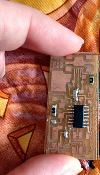
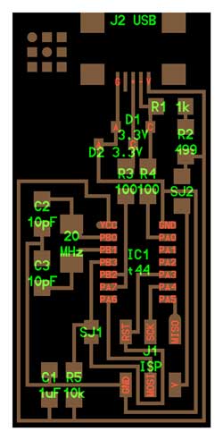
Our TA suggested we write down all of the components we need and place double sided tape next to them and gather components- this was a good suggestion to keep parts in order. Diodes and the microcontroller were the only components where directionality mattered. The C end of the Diode needed to line up with the line on the top of the diode. This was very hard to see. The magnifying glass in the shop was invaluable for aligning parts. Halfway through I realized I downloaded the wrong schematic. Luckily- nothing I had already soldered differed from the FabISP I was actually working on. Be sure to check that your schematics are the same!
I needed to add more solder on some of the pins of the microcontroller. So I did that first and connected it to the computer. This was done a few times until all connections were made. Rob (our fantastic TA) then showed me how to program the board. We used the following steps:
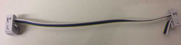
Gather two 2x3 headers and two 2x3 couplers. Line them up the same position. Cut the cable and strip 3 wires off of the cable. Thread through cable connectors and tighten in the vice grip. Make sure the wires line up. Repeat with the other side.
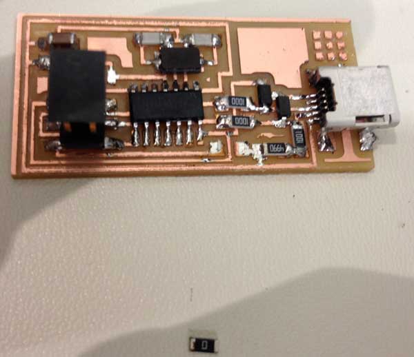
Use the copper braid to remove SJ1 and SJ2. These were located on the board originally to aid in programming and are now no longer needed.

Copyright 2013 Kathy Sinclair