This week we are tasked with measuring something. Adding a sensor to a microcontroller board we've designed creating the board and programming to measure something
Some ideas for this week are
I read once that the key to a long and happy life is unfinished projects. At this rate I'll live to be two hundred and forty.
Neil's hello.load example
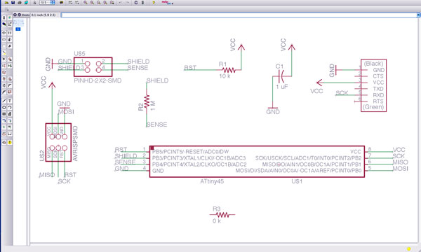
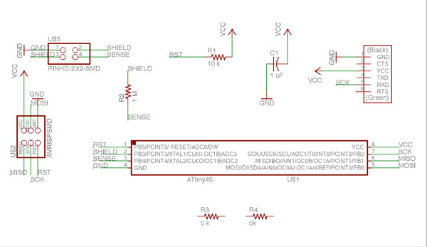
My schematic in Eagle
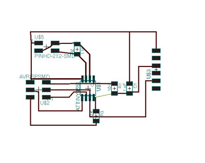
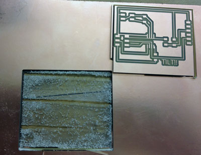
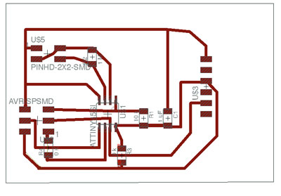
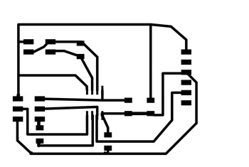
My board in Eagle
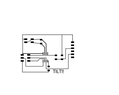
I remember Neil mentioning his favorite sensor could monitor tilt so I figured I could play around with the step response and create a tilt sensor to detect when a person is falling. I used Neil's load hello board as a sample board to design from. I designed the board in Eagle. This still takes me a long time. Finding the right components takes awhile. I then switched to board view and routed the connections manually. I added a 0 Ohm resister as a solder jumper so I wouldn't have too many lines running under the microcontroller. The design rule check looked good. I also used the wrench tool to increase the width of my traces. I thought this worked. But it did not- I later used this tool effectively. The design rule check passed so I exported my board as a png and loaded it into photoshop and added words to the board and a separate board cutout file.
I decided to try vinyl cutting the board again because I thought I'd increased my trace sizes. I adjusted the pen force, speed and the dept th pen was sticking out of the vinyl cutter. I began to cut and noticed my traces were ripping up and way too thin so I abandoned this route for now and decided to mill the board instead.
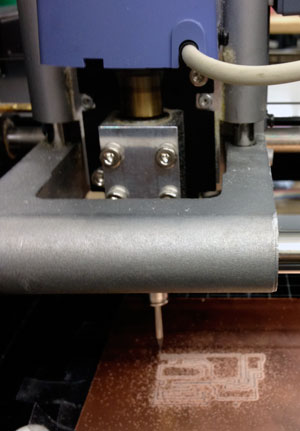
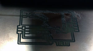
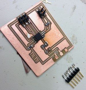
Monday was the first day in weeks that I started to feel human again so I used this night off to mill my board. This took awhile! I don't know if it is because I am still in a semi-sick state and slow or what? The sacrifical layer was uneven. So After a few failed attempts I removed it cleaned everything and reattached it. But then it wasn't stuck down enough and would not cut. So I reapplied sticky tape and reattached the boards. Then I found I was using the wrong bit to mill the traces. So I switched that out. My bit was too dull so I switched the bit again. My board was somehow starting in the middle instead of being oriented in the lower left hand corner so I used a larger board so I wouldn't lose part of my circuit. Finally after many failed attempts I had a finished board. Thanks to Joelle and Rob for help.
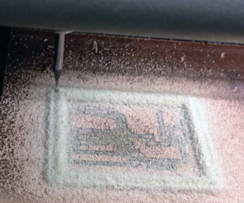
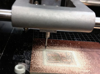
I cut the board out using the board outline I'd created in photoshop and Neil's fab modules.
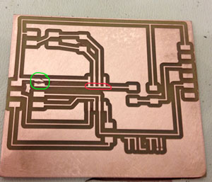
When inspecting the board I found that one of the traces was too close to a pad that it wasn't supposed to be connected to so I severed the connection with an exacto knife. I then washed the board and burnished it with a 360 grit fine sandpaper.
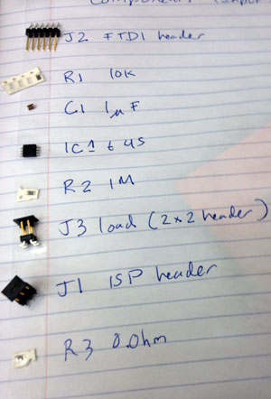
I gathered my parts and placed them on the double sided sticky tape with a label.
I wanted to use lead free solder for my circuit so I found some lead free solder in the bin, turned my soldering up to 825 and soldered away. It was not much worse than regular solder!
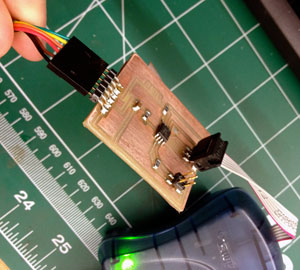
Vivek was around and he helped me an amazing amount with this step. I lost my fabISP and push button circuits earlier in the week. I've been scouring my house for them-- they must be somewhere! But in the meantime we used the storebought ISP and the lab computer and then switched to Vivek's setup with arduino. It failed when burning the bootloader and said to check connections.
I meticulously cleaned up all connections and added bits of solder where needed and tried again. We got a new error and checked the voltage across the microcontroller it wasn't being powered so...
Charles told me that the dot lines up with pin 1. I mistakenly thought pin 1 was the same as pin 0. Wrong! Look at the datasheet!! Pin 1 is actually pin 5. Makes perfect sense right? Opps. Used the heat gun to remove the microcontroller, flipped it to the correct orientation and resoldered it and tried again. Success. 5 Volts were going across the circuit.
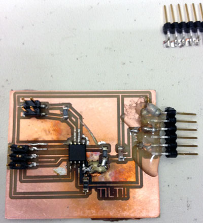
When plugging the ftdi cable in the header the 6 pin connector broke off the board. I plugged in the hot glue gun and while waiting for it to warm up I used some of the earlier vinyl cut traces to patch my missing pads. This kind of worked? but the pads moved around a bit. so I soldered the ftdi header to the board and affixed everything with a layer of hot glue. This took several iterations to get right and Vivek helped with some of the connections.
When I was scraping two connected traces with an exacto knife I accidentally severed one of my otehr traces. So I added a bit of solder to fix this loose connection.
When adding the solder jumper I forgot to add a connection to Vcc. So I cheated and created a giant blob of solder to connect the parts together. Thsi worked and I was getting teh connection I needed.
The circuit was still showing some bad connections when trying to burn the bootloader so I used the heat gun to reflow some solder and hopefully clean some things up. This worked for most connections.
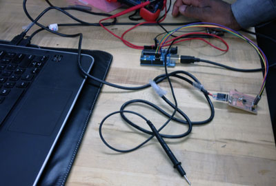
Vivek showed me how to use the voltmeter for debugging and to trace paths and connections. This was an immensely useful tool. Huge Thanks to Vivek for all his help. The ground pin was connected to one of the pads on the board that hadn't been milled away so I severed the connection with an exacto knife and tried the connection again. Success! No more erroneous connection. However, the 0 pin was connected to the 3 pin. I could not fix this or figure out why. It was very late so I decided to hang it up and try again.
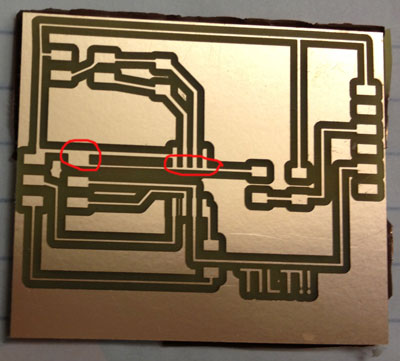
Maybe time to hang it up and start over. I noticed while preparing images for this site that I have all of my pins connected underneath my microcontroller!!
Redesigned board in eagle, beef up traces, add more space close to ftdi header, positioned board so it aligned on lower left hand corner. Add a new solder jumper (0 Ohm resister so my beefed up traces wouldn't merge together.
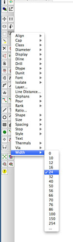
Used the wrench tool, set the width feature and clicked on each individual wire to increase the size of the traces. I added the correct connections as well.
coming soon
Copyright 2013 Kathy Sinclair