006: Electronics Design
This week's goal was to redraw the Echo Hello-world board
Having absolutely no background in electronics and the bad
luck of not being able to attend any of the TA's hours, I had to learn how to put this thing
together from nothing. This is tl;dr list of what I did to educate myself:
- Watched a few of these Eagle tutorials It was helpful to just be
able to see someone click foreign buttons and immediately see the result.
- Read this Eagle Quickstart Guide
This is mostly
just text, so being lazy, I didn't read this until I actually ran into trouble. In retrospect, I probably still wouldn't have read
this first, but I think it definitely pieced together things I didn't understand (e.g., why are there these weird blue lines on my diagram?,
why are things so tiny on the board page?).
- Made a lot of time-consuming mistakes.
And the following is a tutorial I wish someone had written for me when I was
working through this assignment. I had plowed through nearly a hundred people's pages
before I came across something that was remotely tutorial-like.
(Thank you,
benefactor I've never met!) Here we go.
Software
Eagle CAD software
Photoshop, or another image-editing program of your choice
Before using Eagle
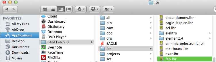
Download the fab library here. It has a lot of the parts
that you will need when creating your schematic. I saved the library in the Eagle library folder.
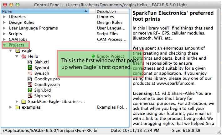
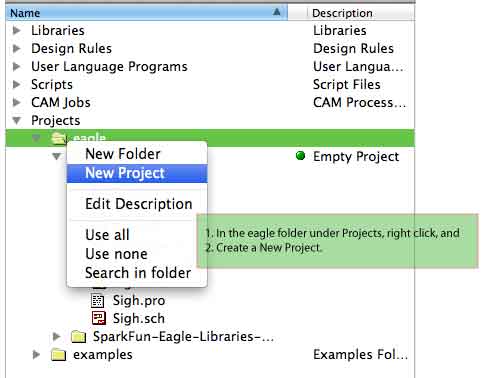
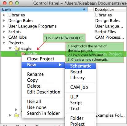
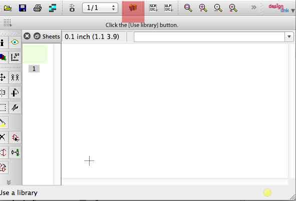
Opening Eagle to make a schematic
- When you open Eagle, create a new schematic via a series of right clicks and new folder
creations. Pictures are worth a thousand words? Check it out:
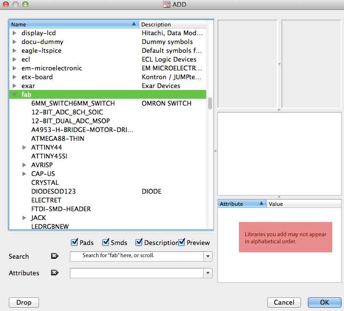
- Open the Fab library before you proceed.

- When you click the Add parts button, you should be able to access the Fab library.

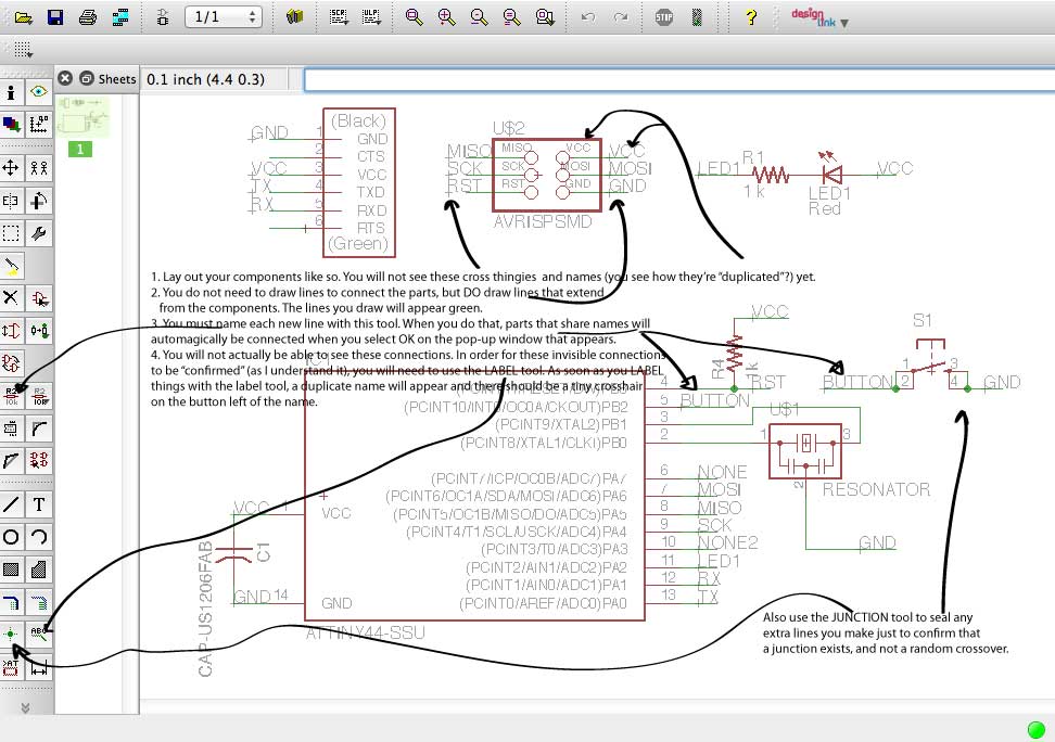
- This is how you lay out your parts.
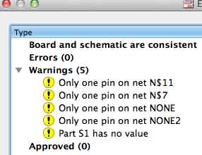
- When you think you're done with the parts, use the Electrical Rule Check tool.

You may see some errors like this. Some pins will be unused, so we can ignore those errors.
But for more serious and mysterious errors, please consult the Eagle Help guide.
- After you've cleared your electrical errors, you can proceed to opening the board.
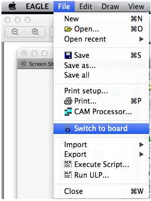
You may be prompted with a message asking whether you want to merge your schematic with a new board. Say yes/OK.
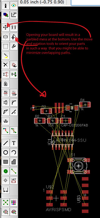
- Now move stuff.
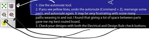
- When you are satisfied, use the Autoroute tool.
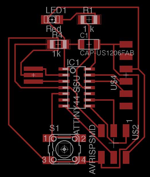
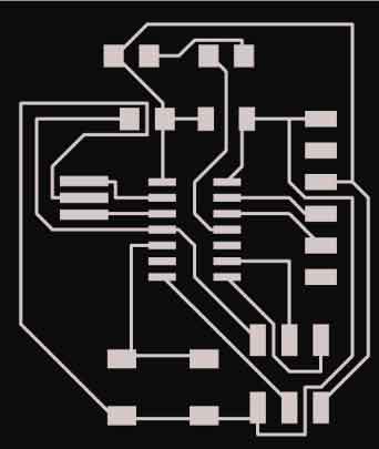
Here is my completed board:
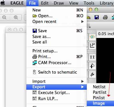
- I exported the board as an image that I saved onto my desktop.
- I opened the file in photoshop and changed the colors such that my traces were white.
Here's a link to a tutorial on how to do that.
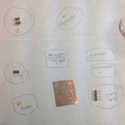
- The milling process was like that of the Electronics Production assignment. Here are my components laid out.
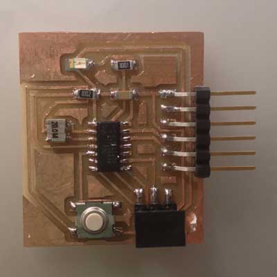
- And my finished product:
I have not yet programmed this yet to verify whether it works.