Final Project
Presence-Aware Mirror
Our final project is upon us and for the last two weeks, I have been working on bringing my idea of a mirror that acknowledges your presence to fruition.
"I have not failed. I've just found 10,000 ways that won't work."
-Thomas A. Edison
While I am very far from the same realm as Edison, this quote kept coming to mind during my final project. I did not try 10,000 ways, but I did try several. In the end, I was able to accomplish my goal, albeit not as elegantly as I had imagined.
I wanted to turn a household object that has one main function into an "interactive" art piece when not being used. A mirror is a perfect example, because when you're not looking at your reflection in it, it doesn't do much.
My goal was to have it (and potentially other hosehold objects), acknowledge your presence in subtle ways. The inspiration is this picture below, of a person running their hand through the grass. When you touch the grass it ever-so-slightly bends with your hand.

Household objects are starting to become more interactive (see
Ambient Technology
's Orb, for example).
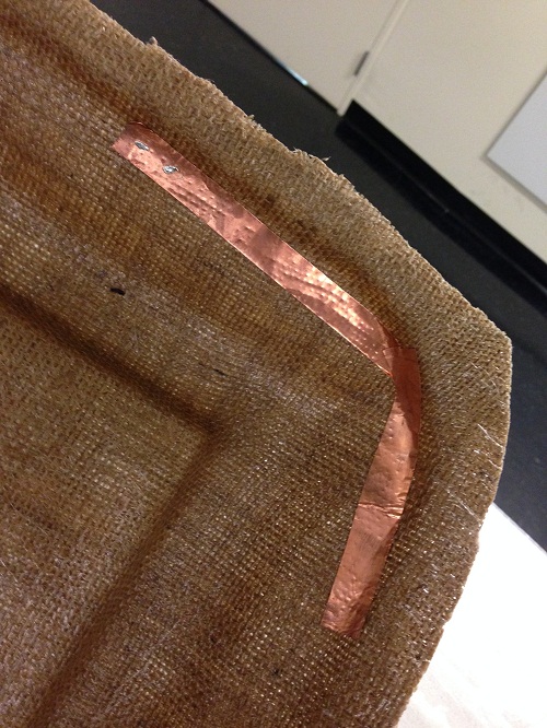
I knew I wanted to sense proximity and after trying several approaches (light sensor, initial investigation with pyroelectric sensor), I landed upon capacitance sensing (capacitance loading). For the testing phase, I used an Arduino UNO to save time building custom boards for each.
Starting with several smaller pieces of copper as my capacitor, I decided to use a big sheet as it got the most differential in readings, and could sense further away. Two, 10k resistors on each node did the trick. Here is one of my failed designs:
I pieced together some Arduino code as a base for writing my code to detect when my hand was near the copper sheet. This approach worked reasonably well, but if I had more time and wanted to perfect it, I would have tried using transmit-receive.
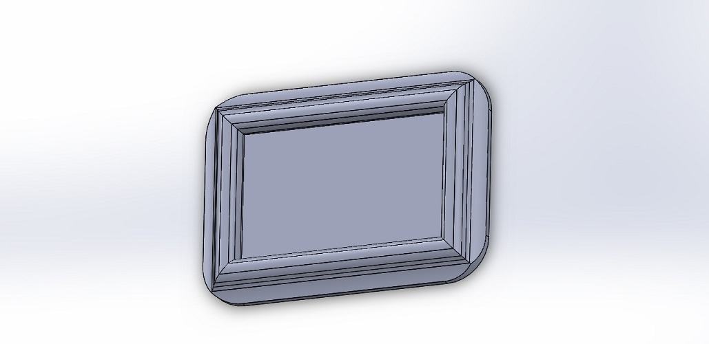
Having decided on my approach for sensing, I outlined the frame in SolidWorks. I wanted it to have an interesting surface that composites would capture.
I decided to use composites after my success in week 8. We had some extra burlap in stock, but I also wanted to try other materials that might be more transparent. I ordered some sheets of cheese cloth on Amazon for $5 for 3 square yards worth. In the end, while it was easy to see through, it looked to fragile so I decided to use burlap.
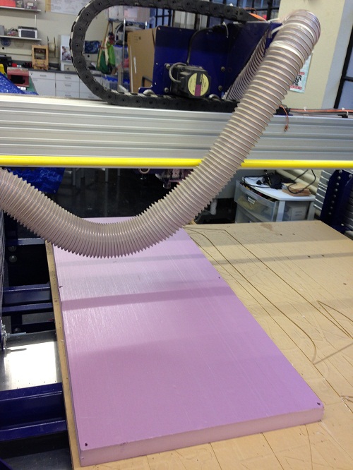
Here is the process I used to create the foam mold (two part) on the ShopBot:
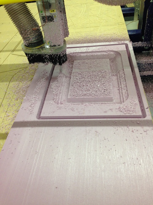
At the end I had this mold:

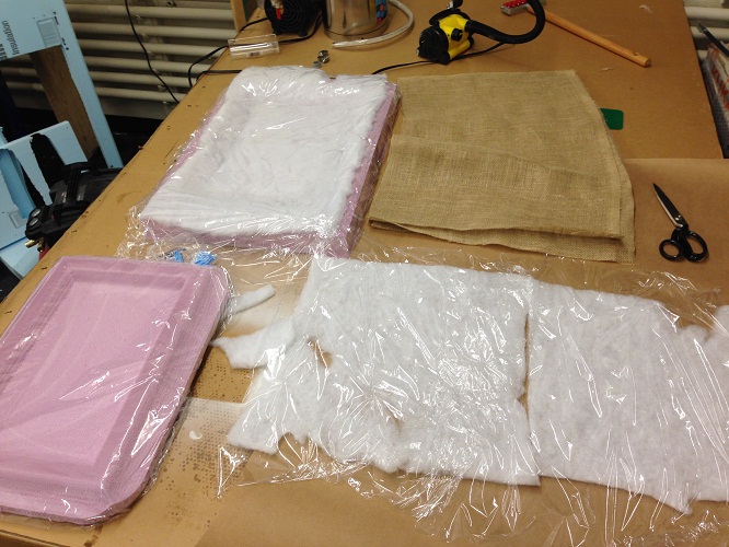
I then followed my same process from week 8, except I used only 3 layers of burlap rather than 5. Since it didn't need to be structrually supportive, this was a good tradeoff to allow some light from the LEDs to come through the material.
Next I laid out the parts and coated the burlap.
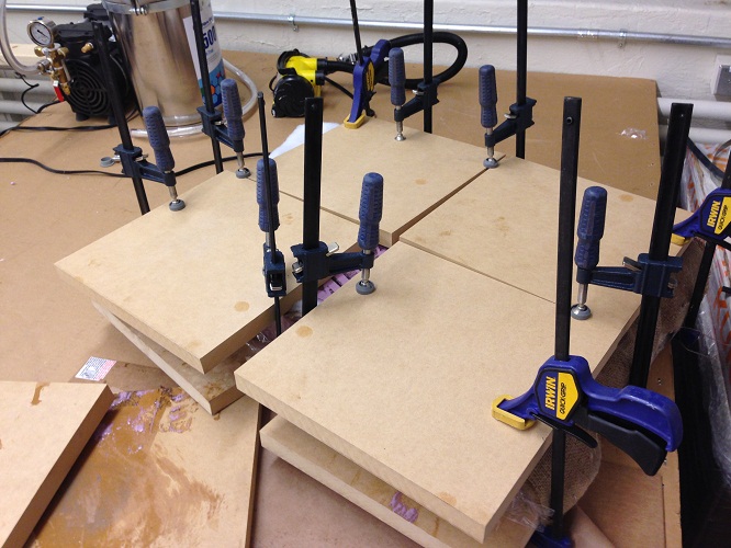
Once done, I then clamped everything using MDF. This was surprisingly more difficult as my mold was much larger this time around. After some trial-and-error figuring out how to keep pressure on the center of the molds, I decided to create a space between some of the 12" x 12"x pieces to put clamps in the middle. I crossed my fingers that this would provide enough pressure.
Fortunatley, when I came back a day later, I unwrapped my creation and... it worked! I used tin-snips again to get rid of the excess boarder and then hand-sanded the edges down (I didn't want to risk damaging the frame with a belt sander).

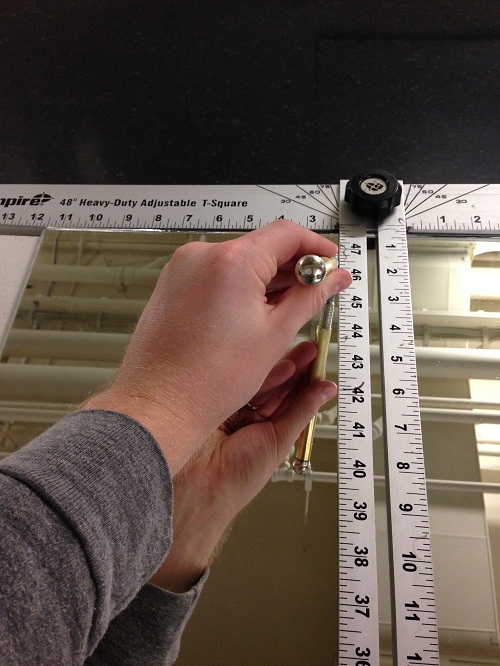
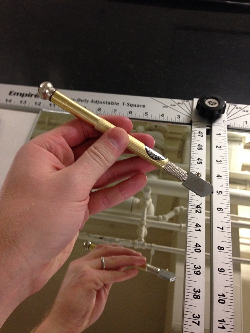
I also had to add the reflective mirror part to the center of the frame. I used an old, frameless door mirror I had, but they cost approximatley $25. I found a glass cutter on Amazon for $6, and using a straight edge T-ruler, I cut it. The tool makes a small cut in the glass, allowing you to break it off rather easily afterward. I had never done this before and it was a very cool experience.
During all these prior steps, I was also iterating around the electronics I would use. I started out thinking Charlieplexing an array of LEDs and putting them in series would work. Once I tried it, however, the lights were not bright enough to shine through the frame and I didn't need the level of control to be able to change each individual LED.
Having enjoyed using the RGB LED in embedded programming week, I created two boards to house these LEDs. I designed the board in Eagle with the intention of connecting it to the main, fabduino board via connectors to the header I added.
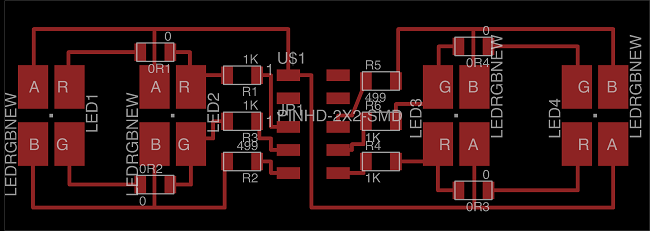
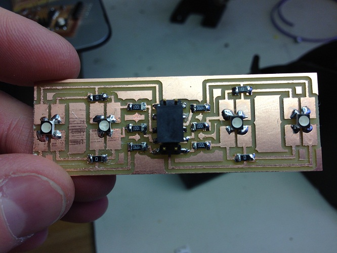
I put two pairs of LEDs in parallel, which required 6 pins for each of the two LED boards. Also needing pins for the capacitive sensor, I used a Fabduino I designed based on the version on the HTMAA website. Changing the design, I re-routed the unused pins to connect to headers I. Additionally, I removed the 20 MHz regulator since I didn't need exact timing.
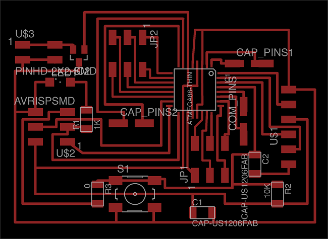
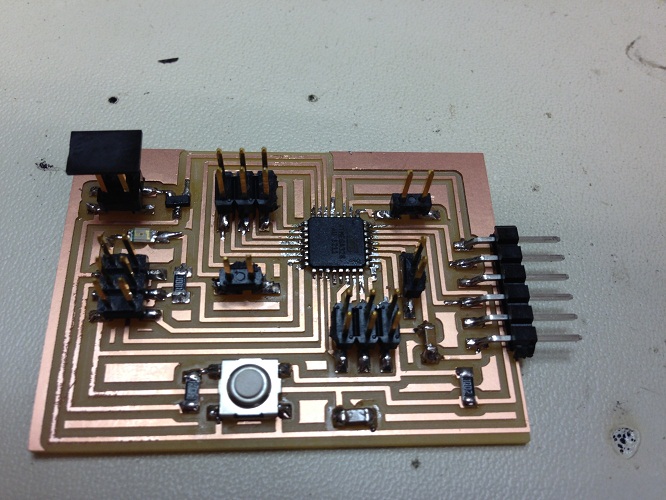
After much work debugging (I had some stray trace overlaps that made it into the first draft of my board, I needed to change the avrdude.conf file to allow it to talk to the ATMEGA328P [ explained here ], etc.). I got it calibrated to work to sense when I was close.
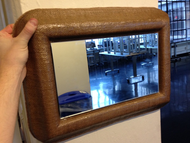
Here is the final mirror with glass attached.
While I wasn't very satisfied with the brightness of the LEDs shining through the frame, I tried another idea, using sandblasted acrylic to diffuse the light more. This was a cool effect, but in the end I didn't have time to implement it.
I consider this a successful project from the frame design standpoint, and from being able to sense proximity using capacitance.
Failures and next steps include:
1) Not being able to put in more LEDs to get it brighter (it is still very dim in the daylight).
2) Because I was iterating throughout the process, getting my boards, etc. to work, I didn't have time to build a rigid structure in the back of the frame to cleanly attach all the boards to the frame. The final version was somewhat hacked together.
3) I had planned on having many more LEDs and using another fabduino board, networking the two of them using I2C. I found a bunch of sample Arduino library code online and was able to get an initial idea working between my fabduino and the Arduino UNO, but I didn't have enough time to add a second board to the frame.
3b) My initial plan was also to add more than one measure of capacitance so I could touch different parts of the frame to have that part light up. Again, however, it became infeasible given how long it took me to implement the basic functionality.
4) Finally, the output I decided on was simply lighting up the LEDs as green when I was close. I would like to add something more interesting, especially given that I went to the lenghts of adding RGBs that could be individually controlled. I had set up the code to create any combination with any timing, but didn't decide on something interesting to do.
Going forward, I would hope to have this type of object in my house, just for the fun/artisitic aspect.
I am very happy with having done this project, and learned a ton not just about the various processes I used, but also about project management: getting each component of the design to work through iterative trial-and-error. This project was also the time that all of the things I had learned in the prior electronics week came together and gave me a much better understanding of how boards actually work. Though it took me several days and nights over the last week and a half to get it done, it was a fantastic learning experience.
Back