Electronics Design
Week 5: Designing, cutting and stuffing my own board
This week our task was to design and make a version of the board we made in week 2, but with an added button switch and a light.
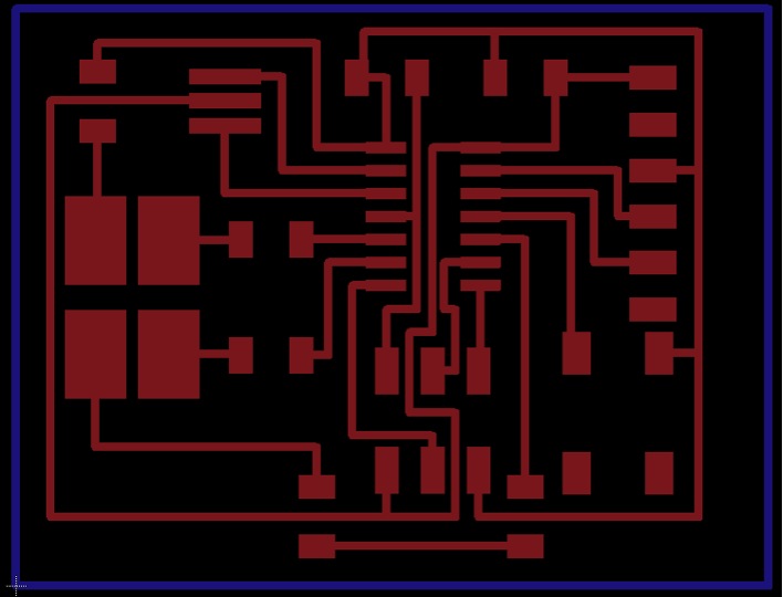
After an excellent tutorial session with Rajesh, I understood the basics of using Eagle as well as a bit of an understanding of how a circuit board actually works (with some recollection of AP Physics). I laid out my board, component by component, in the schematic. While this seemed like a good idea at the time, it got somewhat confusing when trying to connect each part, but after making some initial mistakes, I got a schematic that worked:

I used a RGB LED rather than the regular one because Rajesh mentioned we had them and I thought why deal in one color when you can have three! I then spaced out the components on the board using the helpful "Route" tool. This was great help connecting the right pads together, but it did have low flexibility in terms of where I could place the line (more on that later). Another problem I got into was crossing paths. I tried to design a way out of it, but in the end I used two 0 ohm resistors as "solder jumpers" to connect the RGB LED. I tried to get the whole thing as small as possible, and am happy with the end result, though I'm sure spending more time I would be able to make it even more compact.
I ran the error checker and found only one error where two paths were too close. I also received several "Stop Mask" errors. When I Googled them I found out they are related to the test identifiers of the components overlapping with the route paths. I checked with NovySan and confirmed they weren't a problem so I exported the images and was ready to head to the lab to cut.
Setting up the Modela this time around was much less time consuming than in week 2 (yay, learning curve). I used the same settings as before which were mostly the defaults for the 1/64" bit, but changed the z to -0.13.
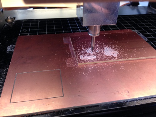
Two problems I encountered were: 1) the interior cutout and 2) spaces between routes.
The interior cut out I had to "invert" the black and white in the image, but the bigger problem was the tool path didn't form correctly (the cut lines didn't connect and only went on two sides). After much time spent trying to diagnose the problem, I realized I had a bit of extra white space around it which, for some reason, screwed it up.
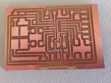
When the final board was cut, I noticed two points at which independent paths were actually connected. Given that there were people waiting to use the Modela, I chose to just cut out the space between them using a knife (surprisingly effective with a steady hand). I realized that these were not detected by the error checker because I didn't change the default tool width tolerances in Eagle. I will change it in my design and will try to cut another board at some point if possible
Given the holiday and the lack of RGB LEDs in stock, I decided to wait to stuff the board until later this week.
So I'm back. I stuffed the board and successfully programmed it in Arduino (much easier for a beginner). One cool thing is that I actually programmed it using the FabISP from week 2.
Note the traces I soldered were much straighter and stronger than on my first attempt with the ISP. Here is the final borard image and a video:
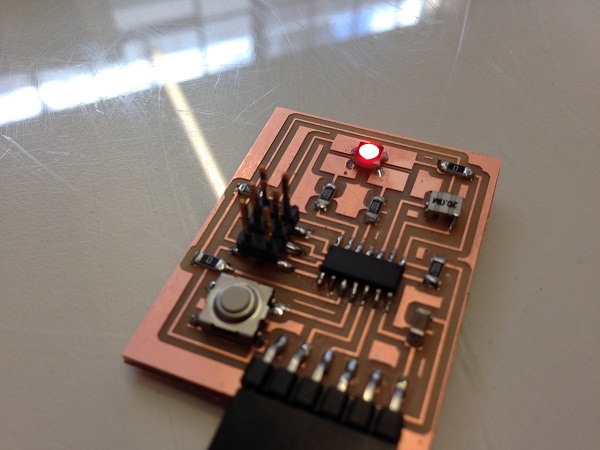
Here is a video of it working! Using the default "blink" and "button" codes from Arduino, I pieced together code to make it blink Red, Green then Blue (RGB). One thing to note, is that with the RGB LED, you have to turn the pin LOW to turn on the LED and HIGH to turn it off (unlike standard LEDs that go HIGH to turn them on and LOW to turn off).
Back