Input devices
Week 9: Measuring something
Our task this week was to measure something.
Since I have an interest in magnets as coupling devices, I have been looking for a way to measure the "pull force" of magnets. Most solutions I found were expensive online and didn't actually measure the pull force (only the gauss field). So I will try to build my own.
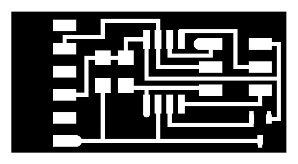
I used the very basic design so I could focus my time on the programming/measurement. Cutting it with the Modela is getting easier week-by-week!
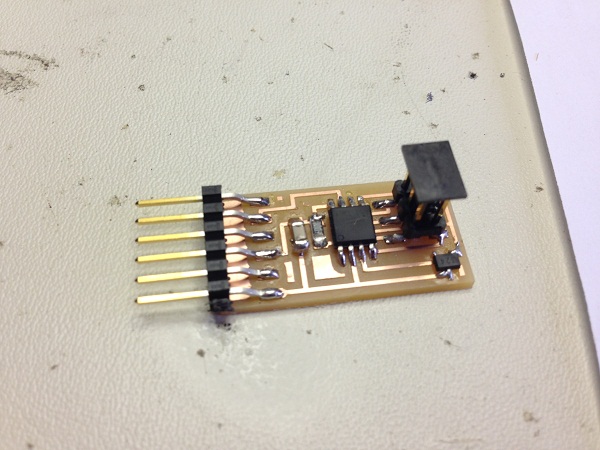
I stuffed the board with almost no problems. This is another skill set that has improved greatly since week 3.
Plugging in the board to program it, however, was my first hurdle. I had been fortunate enough to have my boards work on the first try in the past few weeks, but this was my first experience with a thorough debugging.
In Arduino, I got an error message saying no serial port was identified. With Rob's help, here is was we tried. I include it here only because it was a thorough test process.
1) Check to make sure the AVR light was green (check)
2) Compare the soldered board to the diagram, including the orientation of components such as the ATiny45 (check)
3) Test solder job and shorts with a voltmeter. As an aside: It seemed like one of the Hall sensor pins was connected to ground, but it turned out to be because the FTDI was still connected when testing.(check)
4) Test a new AVR. (fail... not the AVR)
5) Try on another computer. (now it worked! something was wrong with mine)
6) Try the AVR alone plugged into my computer, with the FTDI plugged into another. (also worked)
It seems that one of my USB ports has stopped working with the FTDI cable over the course of a couple of weeks. Not sure why this is, but very interesting nonetheless. This made the rest of the testing/programming process somewhat tedious as I had to keep switching the FTDI cable from another computer to mine to get the board's measurements.
I found some code on the Arduino playground that gave me a good basis to work from. I wanted to create my code "from scratch" as my challenge this week, rather than use the c code provided (though I did try it and it worked beautifully).
Finally, I got the sensor to work after setting a baseline reading. I then figured out the number of "steps" the sensor had (255 plus and minus) and the sensitivity of the sensor (5 mV/G) to figure out what the multiplier constant should be to convert it to Gauss: 1,961 mG / Step. So 1 step ~ 1.9 Gauss.
The next step was to convert this to pull force, and here is where I had the most trouble. Using the "magnet calculator" from a good neodymium magnet suplier: K&J Magnets link. I tried to figure out a similar constant to convert Gauss to pull-force.
What I eventually figured out is that there are more components of the magnet required to convert to pull force, namely the width of the face of the magnet. Interestingly the wider the magnet gets, the higher the pull-force, but the lower the gauss level in the field. With the same face diameter, the thicker it gets, the greater the gauss levels are as well as the pull force.
The bottom line is that with a little information about the surface width of the magnet, I can now calculate pull force. Except...
The sensor seems to only be able to read up to 1,000 gauss. For the 0.99 lb pull force magnets I was using to test, the field was 2,706 gauss according to the K&J calculator. Looks like I will need to find a sensor with a higher threshold for this project.
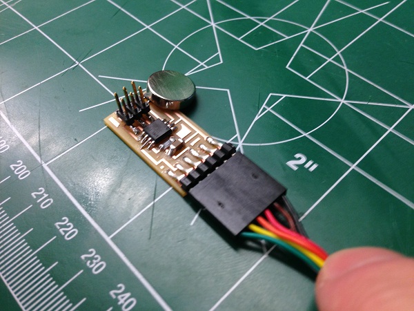
Here is the final sensor working:
Back