Week 11: Output devices.
Assignment: "Add an output device to a microcontroller board you've designed and program it to do something."
Approach for this week:
- Build a simple h-bridge motor control to drive a DC motor in forward or reverse. This will be used in the final project to drvie the spinning machine. Start by following Neil's examples, use the tiny45.
- Learn about PWM, using the built-in function on the chip, or in software.
- Try to use inputs to control motor speed through software.
- Evaluate motor requirements for the project. One motor I have on hand, in a few copies, is a Hall sensor brushless DC motor. I have a back-emf controller for it (does not use the hasll sensors) that works well at high speed, but does not allow the control at low speed that I need. Besides, I did not build it. I will investigate making a hall-sensor motor commutator in software using the tiny44.
1. Build an H-bridge board, following Neil's example in hello.H-bridge.44
Here are my files board, schematic.
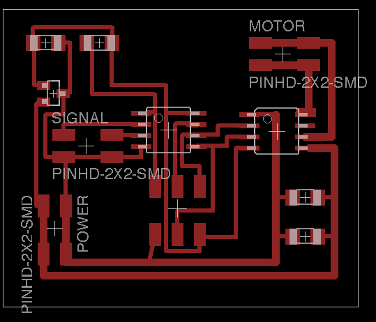
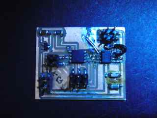
Features of this board.
- Signal input pins 3 and 4, which are physically pins 2 and 3. My intent is to use one signal for direction, the other for speed.
- Output on pins 0 and 1 (in Arduino) which are physically 5 and 6. These pins are used for the built-in PWM function.
- Modifications made to board that are not included in files:
- Ground pin 7 of 4953, the LSS input that is used in current feedback. In the board pictured below, the ground pin of the A4953 is connected to the large copper are at the top or the board, and the LSS pin (pin 7) connected to that with a wire.
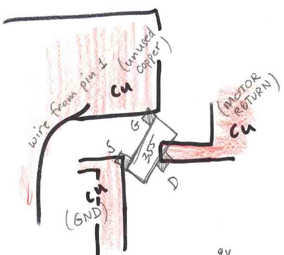
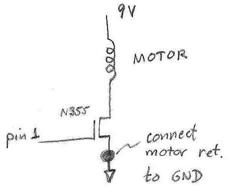
- When troubleshooting, I removed the A4953 board and placed an n-channel FET (the 355: 30V 1.7A in the fab inventory). To do this, I soldered the FET across a fortuitous gap so that its drain was on the motor return and its source on the ground trace. I also had to put a solder blob in the ritht place to connect the motor in lead to the supply voltage. These changes were reversed when I put the A4953 back in. It is not so hard to reroute signals and re-purpose traces and other copper.
2. Problems and lessons.
- I did not pay enough attention to the board design rules, and ended up with non-separated traces that were too close for the 1/64" end mill. I had to cut several traces with a knife. This was quick and successful. Easier to do it right, but nice to know how much can be done with a blade.
- The motor driver chip, A4953 has a pin that I am not using. It is labelled LSS and provides current feedback. I did not connect it to anything on my board, and as a result the chip did not drive the motor. As soon as i connected it to ground, first through a 0.33 Ohm resistor (as on the datasheet) and then directly, the chip functioned.
- While waiting for this epiphany about the LSS pin, I used an FET to drive the motor frum the microcontroller signal (pin1). I picked up the wrong part, and used a p-type MOSFET thinking it was n-type. Did not turn off! All was fine when I used the right part. (NDS355AN). Lessons relearned: When a transistor does not do what I think it should do: 1. Check to see if D and S are switched. Check data sheet to correctly identify S and D. 2. Make sure I have the right part.
3. Programming, using input signals, and results of PWMing.
Simple PWM in Arduino program:
- Once the A4953 was working, I could drive the motor by toggling the pin output in software every second. In doing this, I held one input to GND while the other was raised to 5V. I added a 1 Ohm resistor to the motor leads so that I could monitor current. The circuit, and the result of turning on the motor for one second (the 12V DC motor from the fab inventory) are shown below
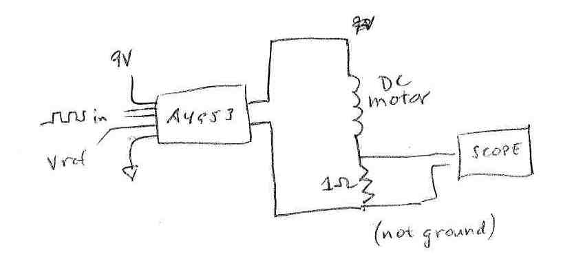
Above the circuit, below the scope trace for a one-second on pulse.
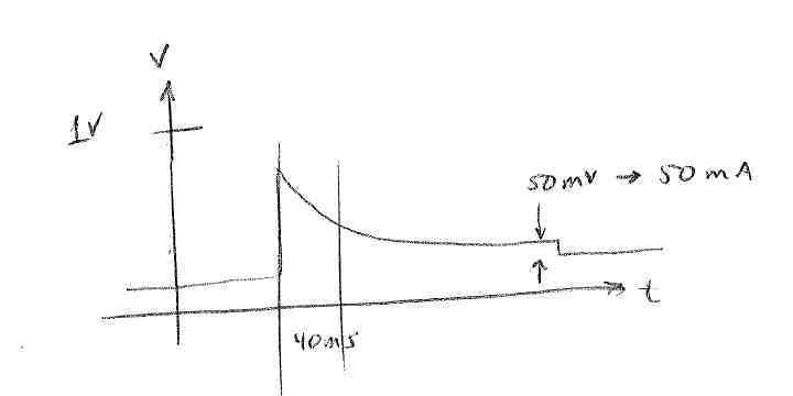
- The scope trace shows an initial fast rise in current when the motor is not rotating, and a fall to a steady-state value of 50 mV (reflecting 50 mA current). The ~40 ms time constant is the acceleration time for the particular driving conditions, and depends on motor inertia and driving torque (In this case ~8V supply, no load on motor). Need to PWM faster than this, anyway.
- Verified that direction is reversed by reversing inputs to in1 and in2.
- PWM with A4953 with a cycle >1 ms. Off time=1000 microseconds, On time varies. Note that the Tiny45 has only one PWM output, so that PWM in software is the way to go if you need two signals, as we do here to drive the A4953 both ways. This is the way that Neil does it in his example with the tiny44, as well.
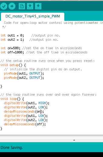
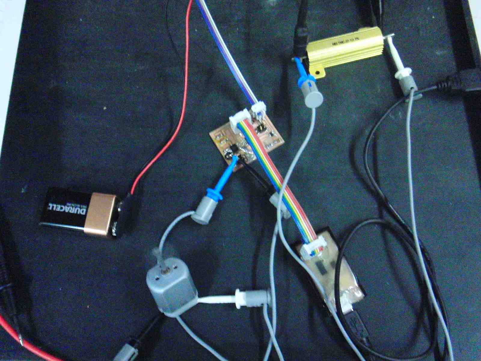
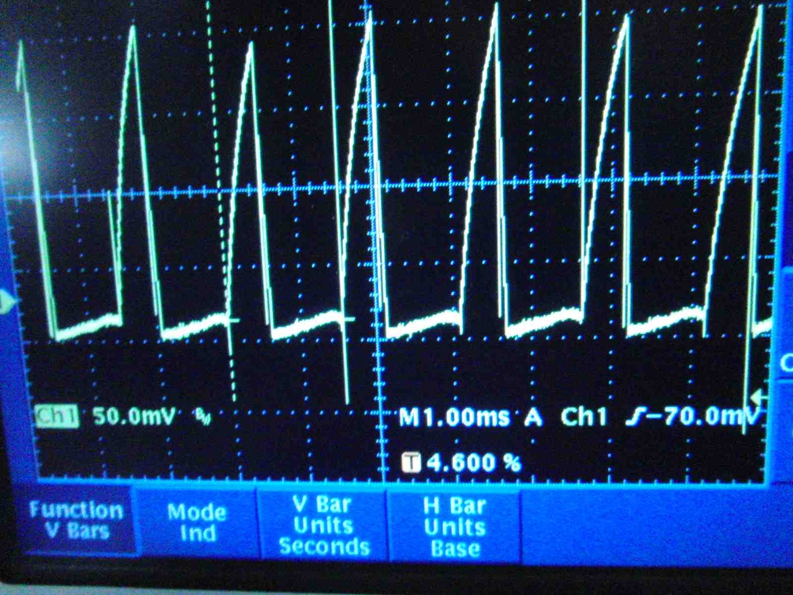
- Motor speed varies as on-time is varied from about 270 microseconds, where the motor just turns on, to arbitraritly long. Below are the board and motor, powered by a 9V battery. The scope trace shown is the voltage across the 1 Ohm resistor in series with the motor, and thus reflects the motor current. The on-time in this case is 500 microseconds, and the off time 1 ms, giving a measured cycle time of 1.55 ms. The current rise time is on the order of a few ms, longer than the PWM cycle. The peak current is about 200 mA, with an average of roughly 30 mA.
Use of input signals.
Troubleshooting:
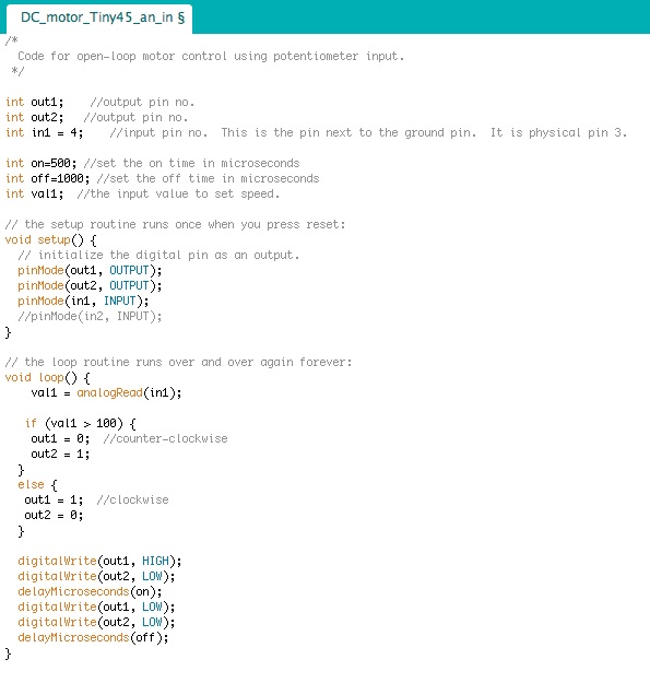
- Motor direction does not change as input to pin 4 is changed. It is always clockwise, as if the analog read value is always zero, even when I connect the pin to 5V.
- It does change when I put a hard value for the analog read in the loop.
- It changes when I increment val1 each loop and change direction when it reaches a threshold - the if statement is OK.
- Here is the code: What is wrong??
4. Motor thoughts related to final project.
- Make some estimates of voltage current and rpm for the spinning wheel.
- Typical operating 5 RPS=300 RPM. My brushless DC motor, with 1:4 pulley diameter ratio, runs at 1200 RPM at 3.6V drawing 0.3 A. (1W)
- Max probably 3x faster, 2x more torque which implies 10V at 0.6A
- The brushless motors that I have are very quiet and may be efficient. They also have a nice shape for my application. They have three phases.( wound in a "Y"??) How to commutate?
- The back-emf controller is not great for ramping at slow speeds.
- In software? Would need three inputs for Hall signals, and three sets of FET's for phases. This could be fun to try anyway.
- Using a driver chip like this one: Hall sensor motor driver chip, A3930 $7 in Quant. 1.
5. Notes from class 11/20
- Taylor Levy worked with video output. Had trouble with timing, using Neil's code. See explanatory drawing in paper notes. avr-libc inline ams cookbook. Do assembly for tight loops and C-code. Try color VGA. This could be done on Tiny44 with limited res. Move to 32 bit for more, as in: Thinner Client VT100 terminal on GitHub.
- JFDuval. Brushless DC motor. Notes on motor control. Neil: Nelder-Mead algorithm to make an optimization loop in software.
- Making solenoids: wind a coil and use rare earth magnets, cut a spring.
- Alice: Humidity sensor. Neil suggests capacitive sensor. Control: overshoot with a step response. Cheesmaking. Would be a nice integrated project.
- IN the tiny45, you can use the reset pin, irreversibly.
- Vinyl cutter: Blade sticks out very small amount, vary force to find correct setting for particular conditions. Alisha on cutting soft circuits. LED's from superbirght LEDs.
- IDC connector: Should not be able to see under a wire.
- Hovercraft also uses brushless DC motors. That is Amir Lazarovitch.
- Mcmaster: Thin garolite sheet for insulation between soldered layers.
- Matthew Keeter last year made a software BDCM Hall commutator?


