Week12: Communication.
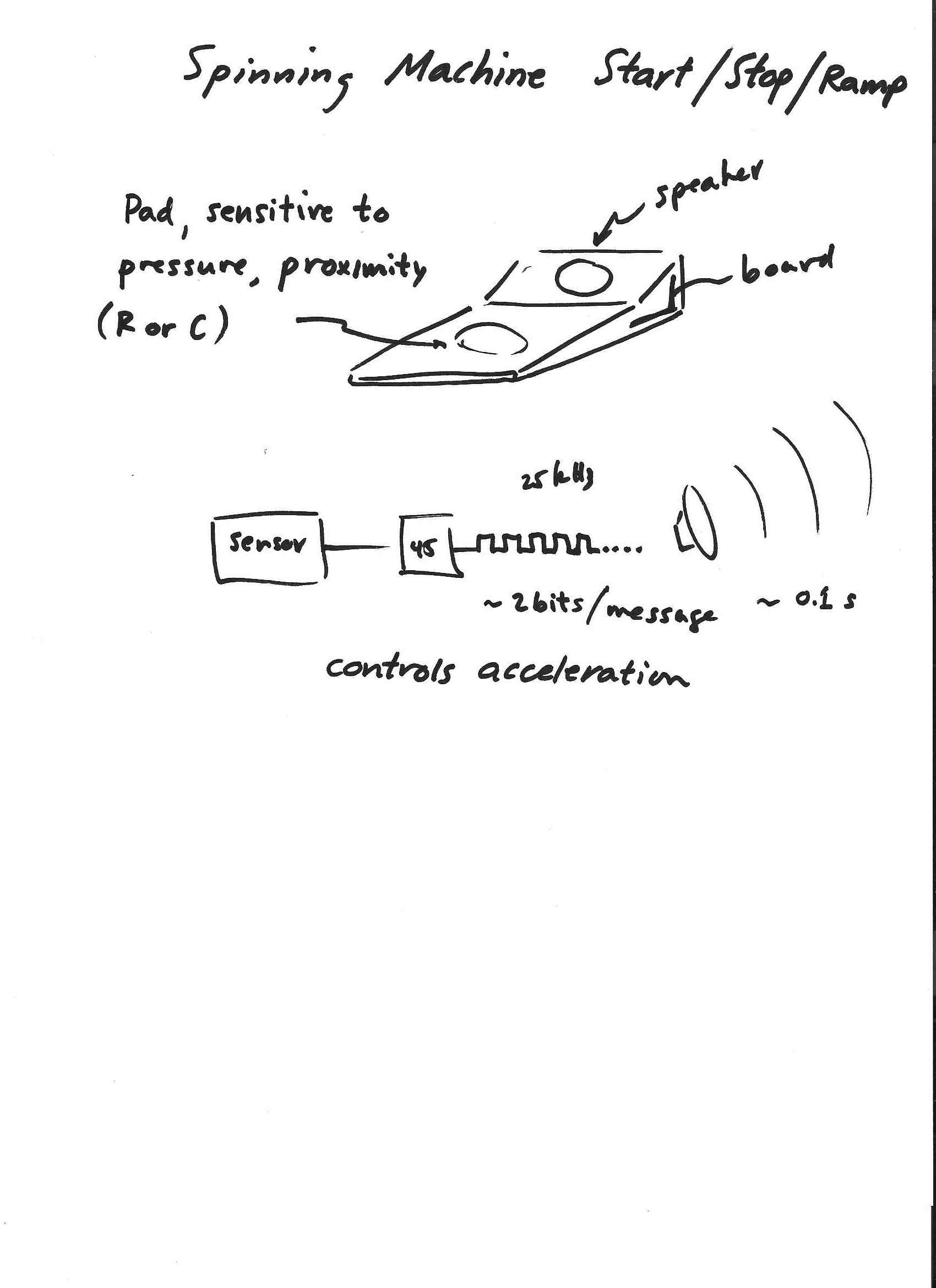
I want to make a wireless link to use in my final project. It will be a foot switch for the spinning machine. Rather than set speed, its function will be to turn on and off the motor. For that function, only one bit is needed! It would be useful, however, to have the switch control the acceleration: pushing hard will speed up/slowdown quickly while a gentle push will produce less acceleration. This might require a two-bit link. It could have four values of acceleration (positive and negative depending on the state of the system) corresponding to a receipt of 0,1,2,or 3. This is a little more than two bits. maybe $0.30. I would like to use sound.
1. Making board.
I made a breakout board for the Tiny44, so that I could have a flexible platform on which to develop and play with software/hardware.
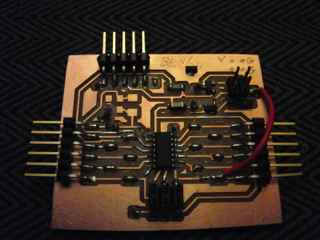
The board, the schematic are here. It has:
- Vias to a ground plane on the bottom side. I drilled them by hand when my plan for modela drilling did not work out. Charles F. suggested that I make a rectangle in the pads layer and put the vias on the via layer. When I export a monochrome png from Eagle using these layers, I get a set of black dots in a white field. I should be able to invert the image and use it with the 1/32" end mill. This did not work immediately, so I opted for what seemed the easy way out. Next time it should work.
- Solder bridges, so that I can choose to isolate the board to some extent. They make the whole thing bigger, so that it does not fit on a breadboard nicely. Probably not a great idea.
- Pads for a 20 MHz xtal and caps, so that the micro can be run with external clock.
- Power can be applied through FTDI cable or external supply with regulator.
- FET to ground for driving things unipolarly.
In the end, I'm not sure that this is a time saver. It turns out to be pretty easy to hack my existing boards for re-purposing rather than have a general-purpose board.
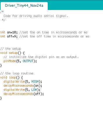
2. Now that I have an externally powered board with a FET, I work on driving a speaker at 25kHz.
- Using the Arduino code I looked at timing for driving and reading. Below is a picture of the code for driving. With total delay time of 19 microseconds, I get a square wave with period 40 microseconds, to a precision of 0.2 microseconds. The signal is not regular - ~1 out of 100 pulses is ~50% longer. This may make detection tricky.
- I checked the timing using Arduino for reading the pulse. Each ADC read takes ~250 microseconds. I need to read precisely every 1/4 period (or N+1/4 period). I think I will need to delve into more direct ways of programming.
- I try to drive the piezoelectric disk that is stocked in the fab inventory. I can get a signal when I use a waveform generator, but get nothing when I drive with a FET to ground using the board. This remains unsolved. How can I drive this thing?
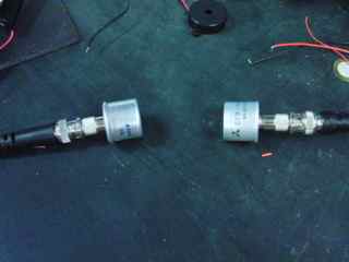
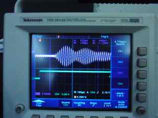
- For my next option, I tried driving the ultrasonic transducer. This is a 40kHz resonant transmitter/receiver, of the same type as the ones in the fab inventory. Initially I thought that they could function as speaker/microphone for my "serial" signal. I found that the pair transmits/receives well when driven at 40kHz, but realized soon that the driven transmitter rings for many cyles after the driver goes away. It can be driven by a step voltage, as shown below, where I applied a 5V step to one device and measured the response of the other. The top trace on the scope is the response. The delay corresponds to the sound delay over the ~ few cm. This could work for communication.
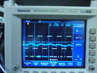
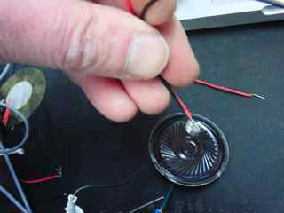
- I have better success driving a small coil/magnet speaker. With the FET board, a square wave drives the speaker at 25kHz. The microphone signal is a noisy sine wave at 25kHz, with lots of audible clicks and buzzes. This will work to develop the next part of the comm. link. Later I can improve the driver:
- See what happens when I toggle pins using simpler libc commands.
- Use the timer/counter function to clean up the wave.
3. Microphone signal and microphone circuit.
- Below is a schematic sketch of neils microphone board. The 10k resistor provides DC bias to the microphone, the 0.1 uF cap blocks the DC level, and passes high frequency, the two resistors, 1M and 5k ensure that the average level at PB4 is vcc*1M/5k = 25 mV. This keeps the signal positive as long as the amplitude is below 25 mV. The Tiny45 board has a differential input to the ADC on pins PB3 and 4 with programmable gain. Neil's hello.mic.c example uses this.
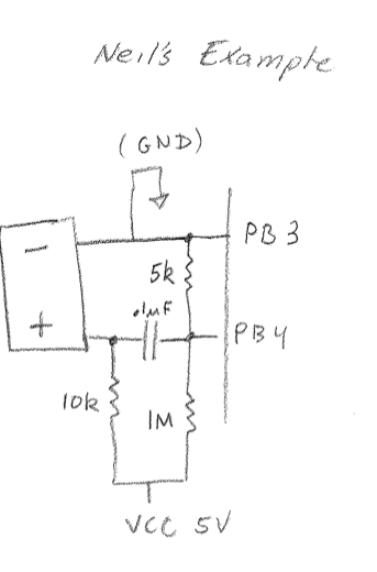
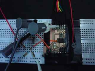
- I modified my input devices board to include a microphone, using the schematic above from Neil's example. The components are mounted off-board. This is one that I will build soon as a dedicated board, with components more tightly arranged around the pins. I am curious to compare the noise level with off- vs on-board connections.
- Signal. About 10 mV at distance of a few cm.
4. Receiving:
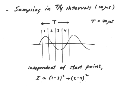
- Method for detecting signal. Quadrature detection.
- Algorithm for detection of bits. Involves detection of signal, and timing of on/off periods. Not yet thought out...
5. Where I ended this week: I now have a board that makes a signal and a second board on which the signal can be detected. This is almost communication.
What I need to do next:
- Receiving:
- Use the hello.mic program from Neil to read the microphone signal.
- Modify that program to detect 25kHz signal.
- Build a board with microphone connections on the board.
- Driving:
- improve the cleanliness of the drive.
- Figure out how to drive the piezo