9/11/13 Work with Inkscape to try for a parametric method. I don't yet understand how to do boolean operations. I try to use intersecting rectangles cloned. Only works on the first pair of objects. Menu indicates that paths are involved, not objects..... This needs more attention. For time being turn to Solidworks, which I know how to use better.
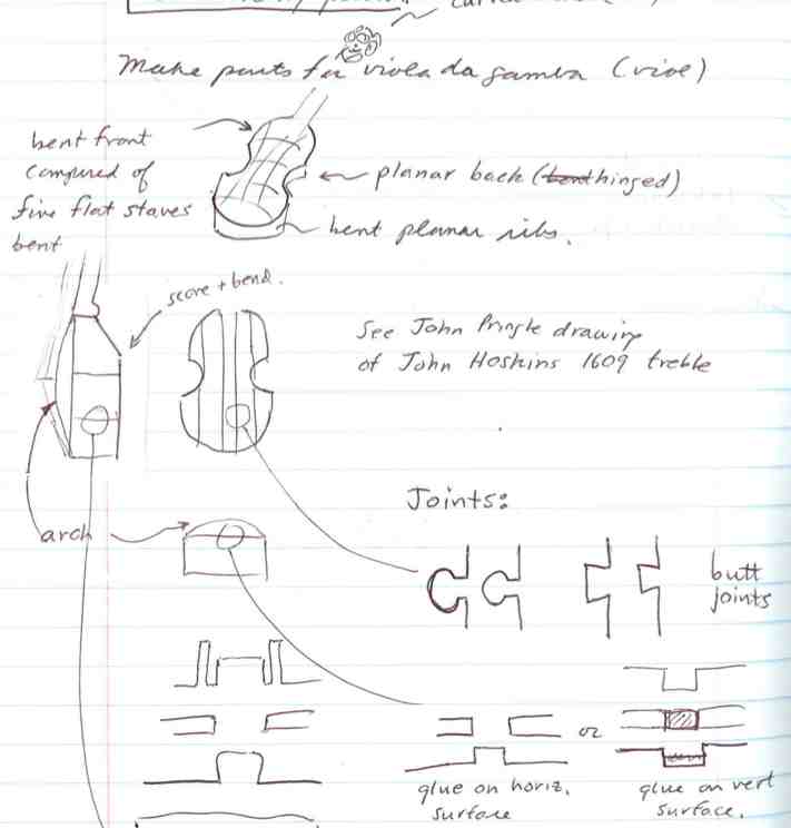
9/12/13 It occured today that the Viola da Gamba, as made by English makers at least, is a 3D structure composed of initially planar parts. I could make a kit for a gamba body:
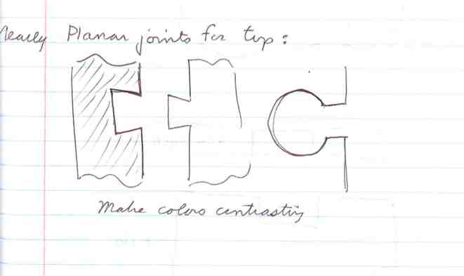
I need to find a way to join parts that are in the same plane (or almost). The joints could be part of the decoration, and alternate strips could have contrasting color.
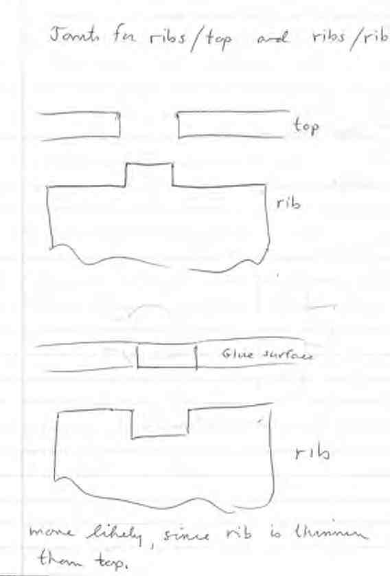
Joints for surfaces that meet at ~90 degrees would have a simple tab. Either interlocking and forming a regular array along the joint, or tabs on ribs pushing through the back and belly. In any case, glue and sand (in the case of wood). Note that it might be best to inset belly into ribs....
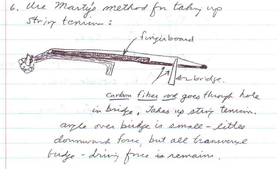 carbon fiber rod takes up string tension and allows control of downward force on belly.
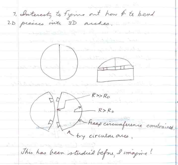
9/13/13.... Learn to use laser cutter on cardboard. First results indicate a kerf of about 0.020". Worked with dimensions to get good tabs for 90 degree joint.
More interesting....I find I can make controlled bends by cutting parallel slits at lower power (Happened to orient such that corrugations are perpendicular to slits)
 This technique could be used to make some interesting shapes. Lines cannot cross, have to go through all material. Radius of curvature locally is related to amount of material removed: R=t/f where t is thickness and f is the fraction of surface removed. In order to make patterns of lines, I need to either us a script-based tool like kokopelli or Rhino(?) or generate svg files with my own code (better?)
Other ideas for vinyl/laser cutter: Flex microscope stage, Scratch holograpy,clock.
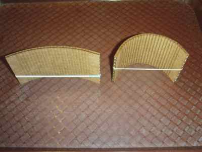
9/17/13 Made Solidworks model of bottom, side and top of a round box. Created DXF files and began to cut on laser cutter. Top is like bottom, except that centerline is an arc of radius 30" (about 10x box radius). Result is a cone about 2 cm high at center. Cardboard may be too stiff to bend this way - may need radial cuts. i think I'll need to adjust the interlocking bits - too many approximations for it to work the first time. Sides will have scored lines to allow bend. First try generated a fire - I will go more carefully next time. In the meantime, here's a paper trial of the sides and top. Close.
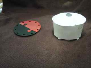
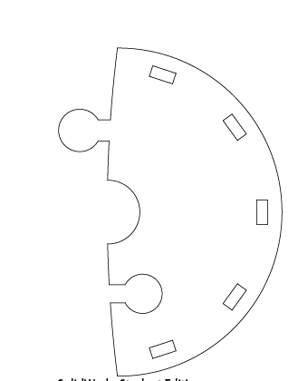
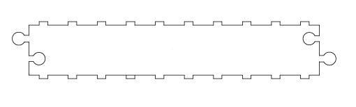
9/19/13 Cut cardboard version. Radius of side not quite small enough. Top does not join well because joined edges are an arc, which corresponds to a dome rather than a cone. But with a little persuasion, extra cuts, and tape on the inside, it doesn't look too bad.
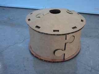
Here's what I want to do for the next iteration:
9/24/13 Here is a simple way to make *.svg files. Refer to the *svg Primer on the w3c.org website. Also use the kokopelli output files which give an example of setting a scale. My Matlab script writes a text file, "pepe.svg". Nice thing is that between editing and seeing the result in a browser is about two clicks.
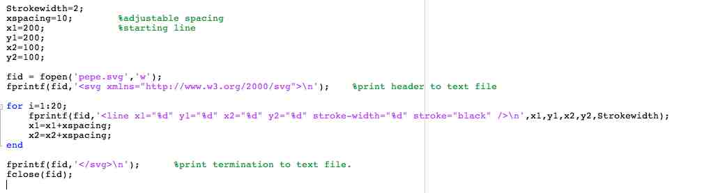
Here is the svg file:
<svg xmlns="http://www.w3.org/2000/svg">
<line x1="200" y1="200" x2="100" y2="100" stroke-width="2" stroke="black" />
<line x1="210" y1="200" x2="110" y2="100" stroke-width="2" stroke="black" />
<line x1="220" y1="200" x2="120" y2="100" stroke-width="2" stroke="black" />
<line x1="230" y1="200" x2="130" y2="100" stroke-width="2" stroke="black" />
<line x1="240" y1="200" x2="140" y2="100" stroke-width="2" stroke="black" />
<line x1="250" y1="200" x2="150" y2="100" stroke-width="2" stroke="black" />
<line x1="260" y1="200" x2="160" y2="100" stroke-width="2" stroke="black" />
<line x1="270" y1="200" x2="170" y2="100" stroke-width="2" stroke="black" />
<line x1="280" y1="200" x2="180" y2="100" stroke-width="2" stroke="black" />
<line x1="290" y1="200" x2="190" y2="100" stroke-width="2" stroke="black" />
<line x1="300" y1="200" x2="200" y2="100" stroke-width="2" stroke="black" />
<line x1="310" y1="200" x2="210" y2="100" stroke-width="2" stroke="black" />
<line x1="320" y1="200" x2="220" y2="100" stroke-width="2" stroke="black" />
<line x1="330" y1="200" x2="230" y2="100" stroke-width="2" stroke="black" />
<line x1="340" y1="200" x2="240" y2="100" stroke-width="2" stroke="black" />
<line x1="350" y1="200" x2="250" y2="100" stroke-width="2" stroke="black" />
<line x1="360" y1="200" x2="260" y2="100" stroke-width="2" stroke="black" />
<line x1="370" y1="200" x2="270" y2="100" stroke-width="2" stroke="black" />
<line x1="380" y1="200" x2="280" y2="100" stroke-width="2" stroke="black" />
<line x1="390" y1="200" x2="290" y2="100" stroke-width="2" stroke="black" />
</svg>
Here is the output as seen by a browser:
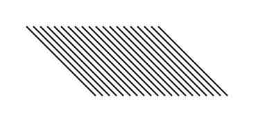
I need to learn how this translates to real units. An example is in the kokopelli output *.svg file.