 socket002 x-section
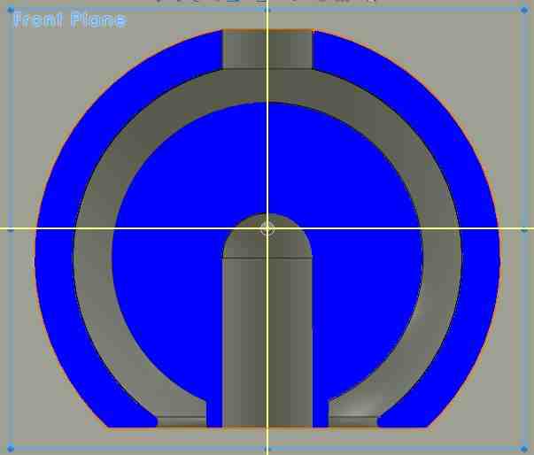 socket002 built
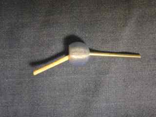
I would like to make a captured rotating bearing in the form of a ball and socket. I use Solidworks and the Makerbot Replicator2 in the Harvard Science Center physics teaching labs. Start with a simple concentric sphere design, including holes for 1/8" rods to connect. Questions to guide iterations:
In all the models below the quaility is set to standard in the Makerware software, and the software defaults are chosen for other options.
socket001 socket002 x-section socket002 built
Round 1: In the first set of sockets I make a thin support extending down from the inner ball. Inner diameter of all interior balls is 0.50". Due to the low surface area on the build plate, the objects do not stick well to the blue masking tape. Building on double-stick carpet tape solves that problem - adhesion is better. Hole size for insert: design size 0.125" gives actual hole 0.105". Hole size of 0.145" diameter in the design for socket002 gives slightly oversize hole in the top and about right in the bottom. Range of motion is ~30 degrees.
socket005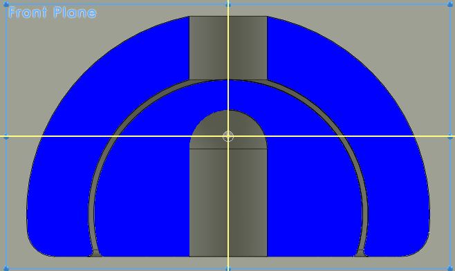 socket009
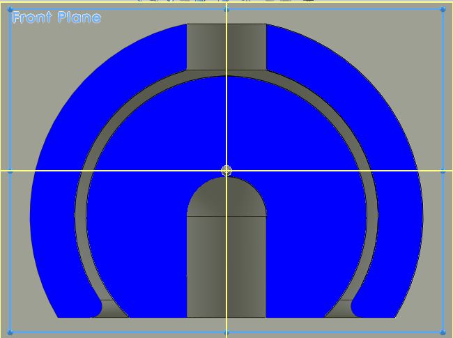 socket009 built
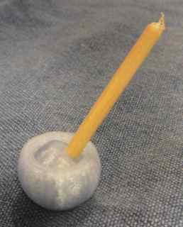
Round 2: Settled on hole diameter of 0.142" - about 0.017" oversize. Change to a design that has more surface area in the first layer. Looks like it should allow more range of rotation as well. In the build, this sticks much better to masking tape. Now investigate size of gap between spheres. Radial gap of 0.010" (in socket005) is too small - the two spheres do not separate. Not a surprise. Gap of 0.030" and 0.025" are loose. For this design a gap of 0.020" seems about as close as possible to allow smooth motion (about 0.50 mm). Note that this is also a function of the design, since the unsupported overhang probably doesn't hang together very well. For a vertical cylinder, this gap could probably be smaller. Range of motion is about 40 degrees for socket009.
Now for fun, make a rod extending from the top to make a chain. In order to make this come out to diam. 0.125" my first guess was to undersize: design diameter 0.110" comes out 0.104". Second try, make it 0.125", and get 0.120-0.130. This fits for most parts.
Socket010 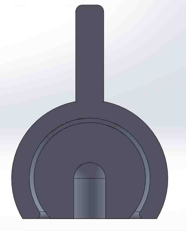 .Chain
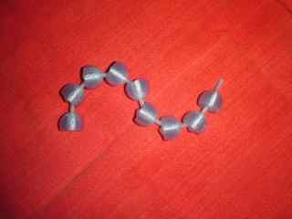 Another chain
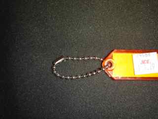
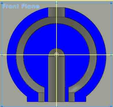
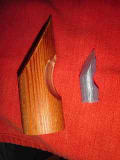
Above, the cross section of the SolidWorks model. The chain of socket parts. The same idea, made with sheet metal and wire. Nice design!
Here's what I learned about dimensional gaps and tolerances on this part, made with Makerware 2.2.89 on the Makerbot Replicator2. Standard quality, other settings default. Diameter of inner ball 0.050".
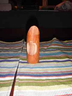
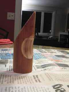
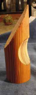 Here is an object made from a 1.5" round ,wood rod. It is a simple shape, so that it can be modelled by two cylinders and two planes. It is non-reflective, and has some detail (I may need to add more). This gives the optical scanning methods a better chance to work. Here's what I try:
1. 3D scanning part 1. 123D Catch.
Using my wood cylinder, I tried the online version of 123D catch. I circled the object, took and uploaded ~30 photos.
 An example of the picture group on the left. The result is on the right.
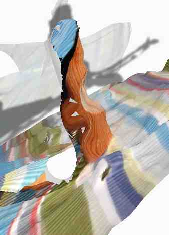 The project built, but was distorted and had many holes. Likely problem is my use of the flash. This gives lighting that changes from photo to photo, and doesn't stitch toghether well, of course.
Second and third tries with more consistent lighting did not build a project. A fourth try using the iPad app and photos from the iPad worked well and quickly. After uploading the photos the 3D model was computed in a few minutes. I was able to view the project on the iPad app and on the website. I did not succeed at opening the project in the online window for editing. I downloaded the app for PC and ran it on Windows, hoping to be able to download and edit there. I did not figure out how to import a project into that application. I did succeed at opening the project online and downloading an stl file. {Late note: a few days later I am now able to open the project and edit online. I installed the browser app (Firefox) that allows mesh editing. Looks promising.}
Here are the tips that seem to work, from the 123D catch website and from others:
I was able to import and edit the stl mesh file in Meshlab, which I installed on both Windows and Mac OSX. This looks like a powerful tool - it can import and export mesh files in many formats. I used it to import a binary stl and export it as ASCII. I could then see the structure and could potentially edit and resave the file. It was easy to eliminate mesh points, but not obvious how to add and repair mesh. it should be possible to get it to work - there is lots of information out there on the use of this tool. We should probably put together a tutorial on this for the FabClass. Note that Meshlab crashes consistently on my Mac but is fine in Windows. Other in the class (and on the web) report similar crashes.
1.  2.
2.  3.
3. 4.
4.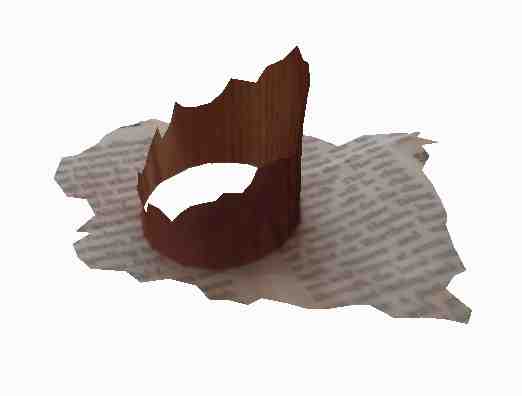
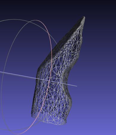
Results shown in the above figures: 1. Photo used as input for the 123D catch project. 2. The downloaded stl mesh, as edited in MeshLab. I trimmed off the newspaper, but did not figure out how to make a new bottom plane. Not exactly watertight. 3. The stl file worked on the Makerbot anyway - I pushed the model into the build plate (in the GUI) and hit the build button. There was some confusion in the first two or three layers - the first layer was only about half there, but it did build. The model is lumpy, but it works. 4. Another cubist creation from 123D catch, after my recent editing.
What I learned:
What I want to learn next: Editing in 123D catch. Better use of Meshlab for simple repairs and additions to stl files. Perhaps a useful Tutorial subject.
2. Scan an object part 2: The laser pointer 3D scanner.
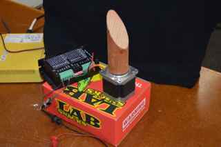
I made a scanner for my cylinder object using a laser pointer and a stepper motor. The stepper motor is controlled by a function generator square wave to rotate the object once per second. This is very precise, limited by the device's clock. A laser pointer illuminates the object, and is translated vertically. A camera views the object at an angle of about 60 degrees from the laser beam direction. As the laser beam is translated upward on the rotating object, the camera records a movie at 30 fps.
1.  2.
2. 3.
3.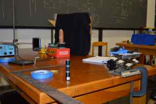
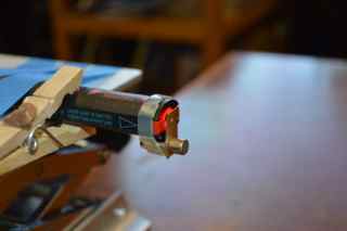
Above is what it looks like: 1. The laser pointer. A brass sheet with a pinhole, held in place by magnets, keeps the beam diameter about one mm at the object. It is tranlsated vertically with the labjack that it is taped to. 2. The stepper motor and controller. 3. The setup. Camera is to the left of the obect. The laser spot is dimly visible near the bottom of the object.
1. 2.
2.  3.
3.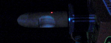
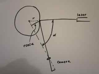
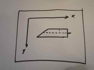
The sketch in 1. above gives the geometry, as seen from above the table. The apparent position of the laser spot on the object is proportional to r times the cosine of the angle between camera and laser beam. In the recorded movie frames, the coordinate system is as shown in 2. An example of a frame from the movie is shown in 3. By locating the laser spot in each movie frame, the radius of the object can be inferred as a function of distance, x along the axis and as a function of time. Since the rotation angle as a function of time is known, data on r,theta, and x on the surface is collected.
I wrote a Matlab script to analyze the movie. Here are the files as they stand now for Analysis and for Coordinate Transformation. Here is what it does:
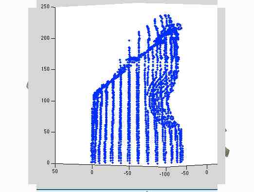
Here are some graphs to show that I'm getting somewhere:
(1)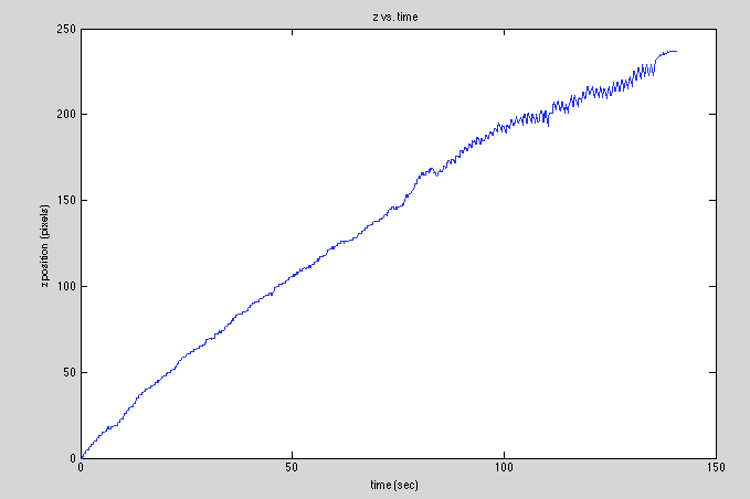 (2)
(2)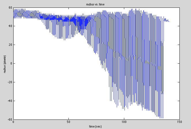
(1) is a graph of z(t) to show that I was able to pick points correctly. (2) is a graph of r(t) that shows the correct behavior (I think) as the laser sweeps along the cylindrical cutout and the planar top.
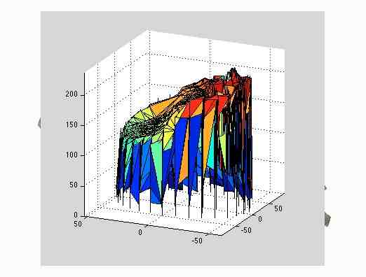
Next I will figure out how to visualize this in 3D as a set of (x,y,z) points. Matlab should do this. Then I need to turn my cloud of points into a mesh. Among the possibilities: