Final project: Smart tennis racket sensing system
I wanted to make a smart tennis racket with sensors to give beginner tennis players feedback on their play technique
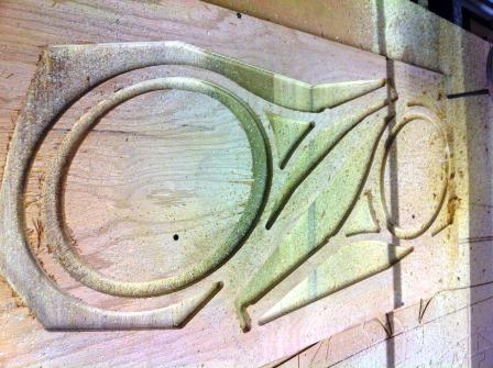
Tennis racket design
I did this in the composites week. I machined two halves of a tennis racket out of plywood with a CAD model that I made. I did not manage yet to string it although I hope to do so soon.
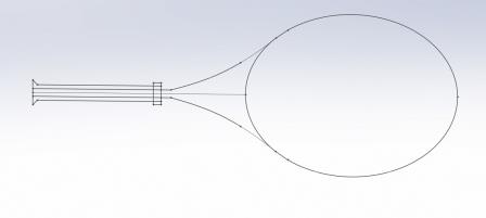
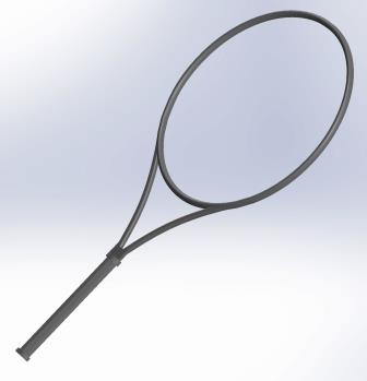
Tennis racket cad model
End Milling setup with 1/2 inch ball end mill. I followed Sam's example from last year.
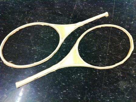
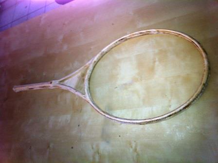
I milled the two symmetric halves and glued them together using gorilla glue. This is just a shape layer, with little strength. Some of the parts are broken actually. We'll see how strong it is once the composite is laid on top of this
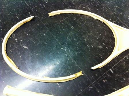
And we have a tennis racket base!
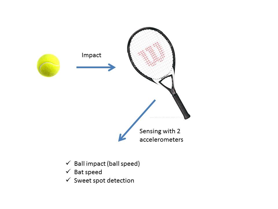
Sensing system
I wanted to use two accelerometers, one low g 2.5g 1-axis accelerometer MMA1270KEG and one high-g ADXL377 200g accelerometer to detect the ball impact and the user swing speed. The concept was to use the information from the 2 accelerometers placed apart from each other and triangulate the position of the ball on the racket. I still need a third accelerometer or some information about the relative orientation of the two accelerometers to figure this out exactly.
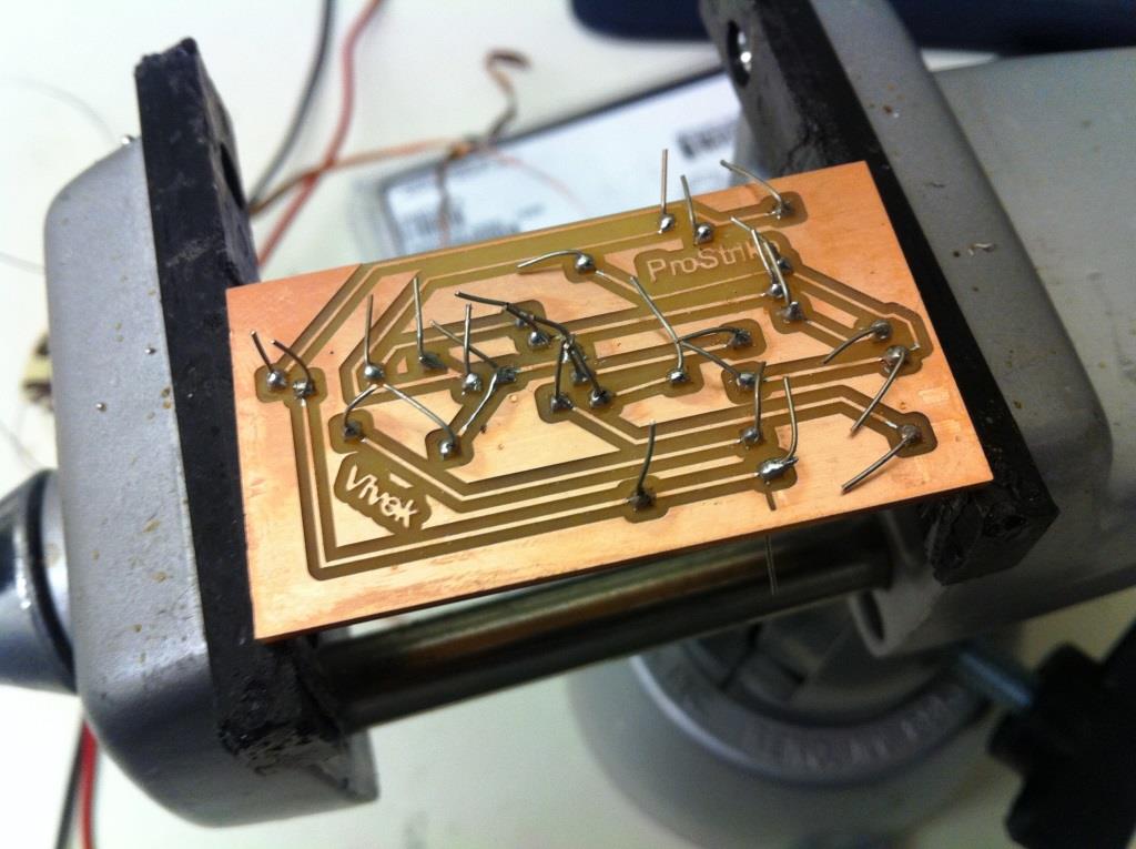
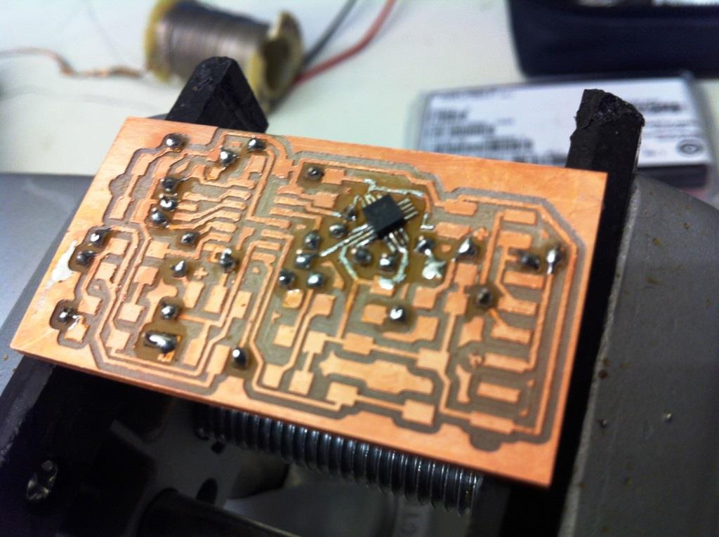
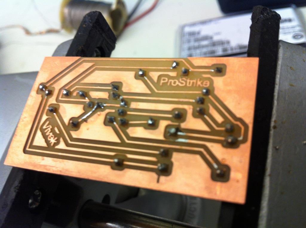
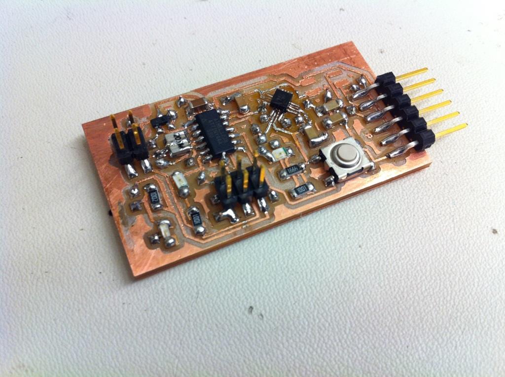
The 1-D accelerometer
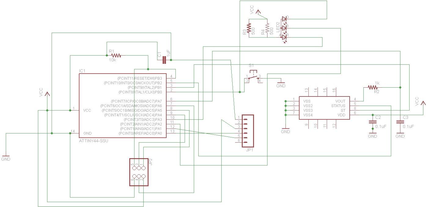
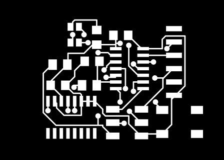
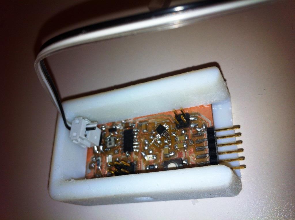
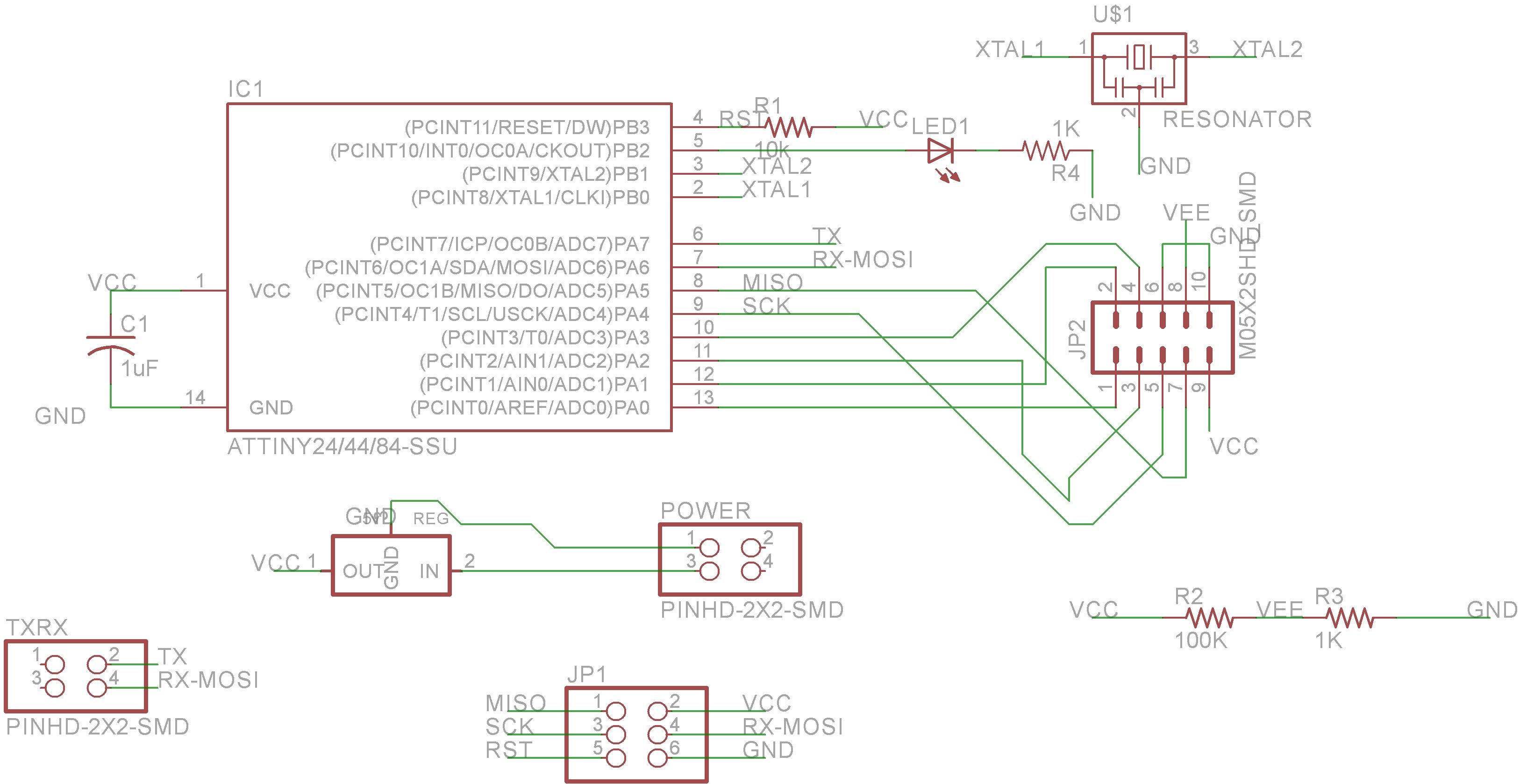
I designed this system so that the light changed depending on user bat acceleration so that when the acceleration is high the led changes from blue to red.I made a two sided board with the ATTINY44 with a 1-axis analog accelerometer MMA1270KEG.

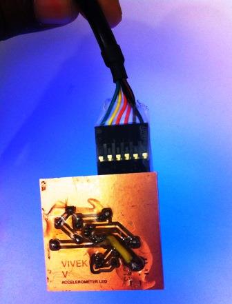
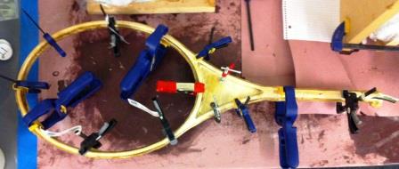
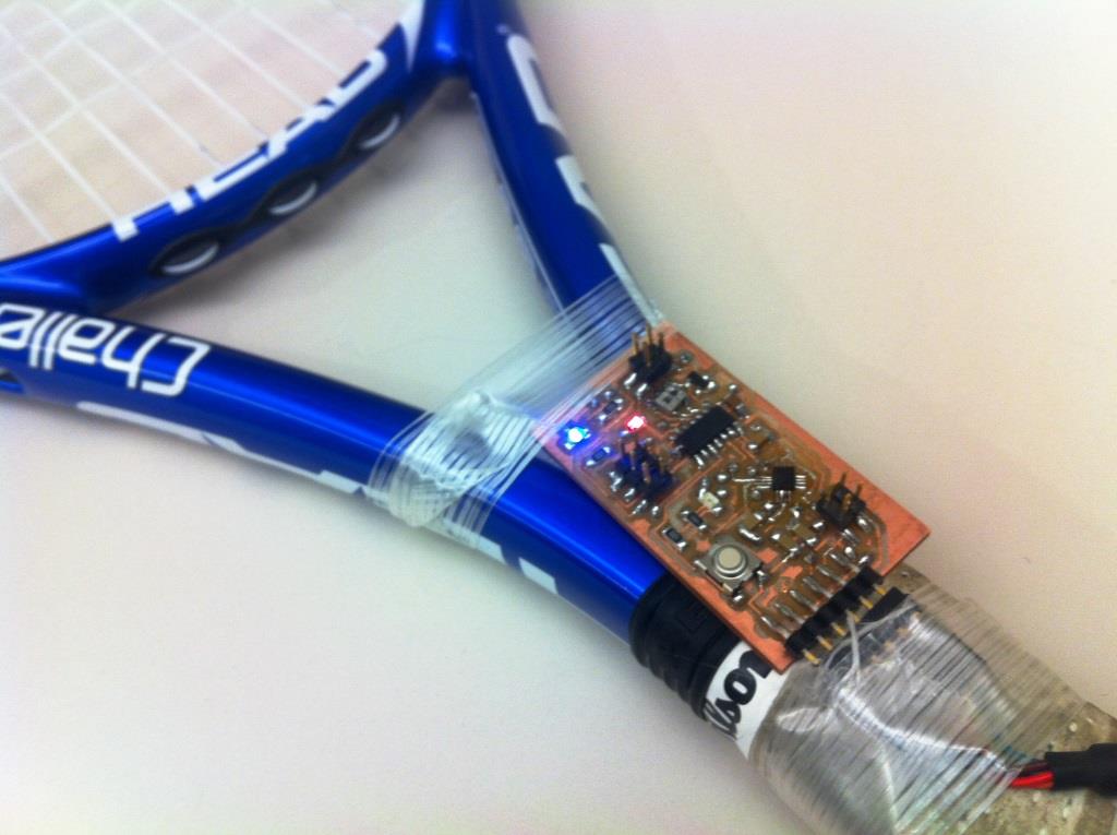
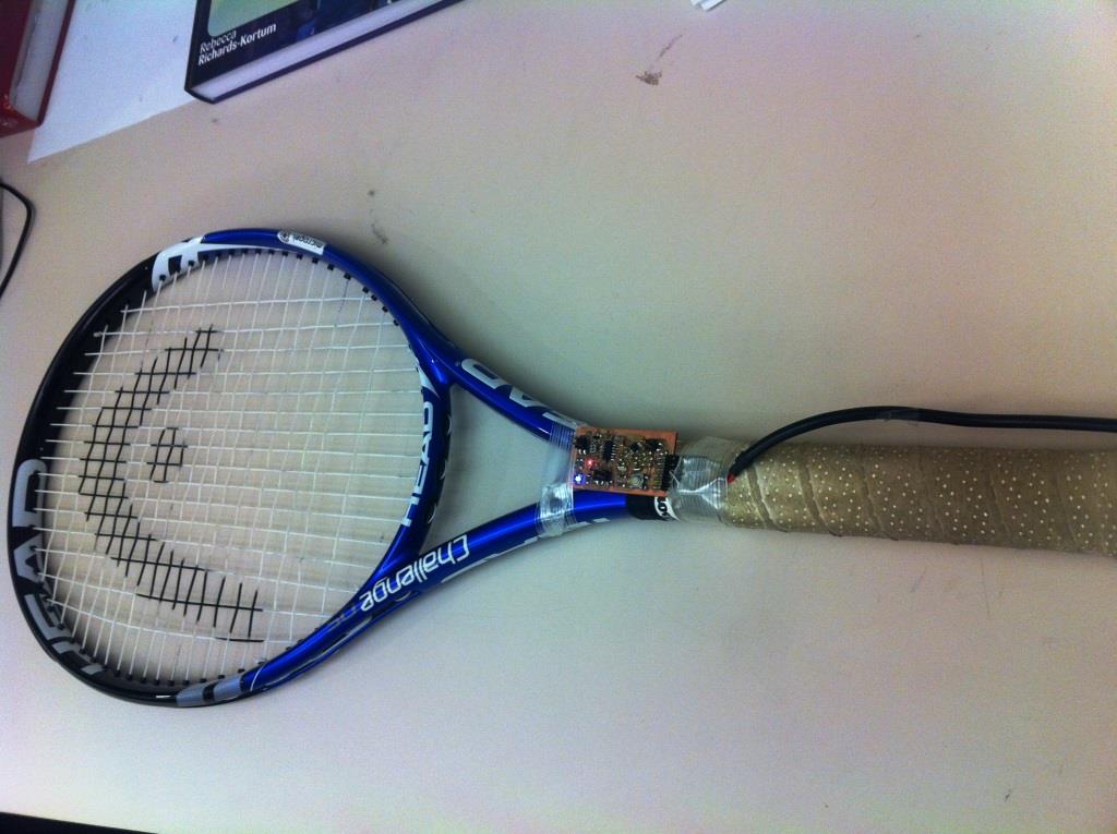
I attached this circuit to the tennis racket frame I made last week.
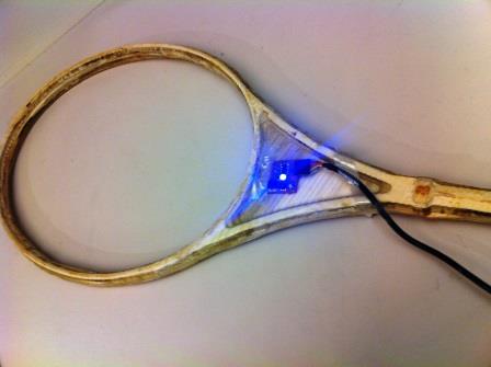
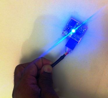
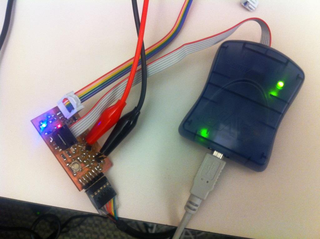
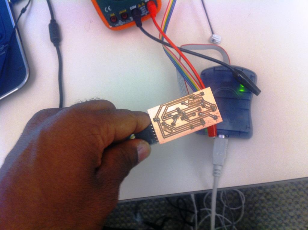
Demonstration and visualization of output from the Accelerometer read by thr ATTINY44 ADC and then serially transmitted
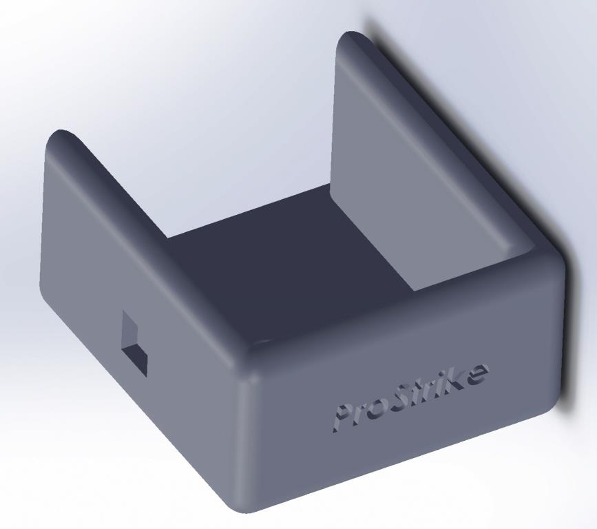
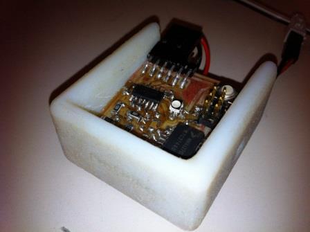
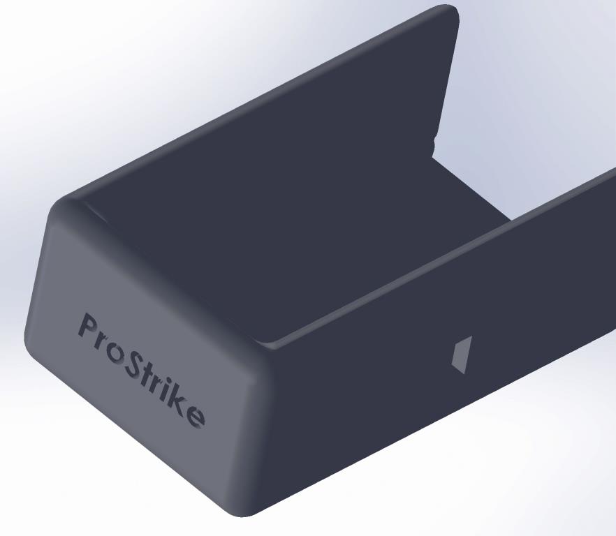
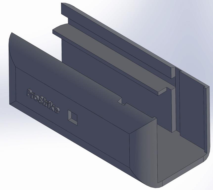
I then 3D printed a casing for it to eventually clip on to the tennis racket. Here is a demonstration of the blink response.
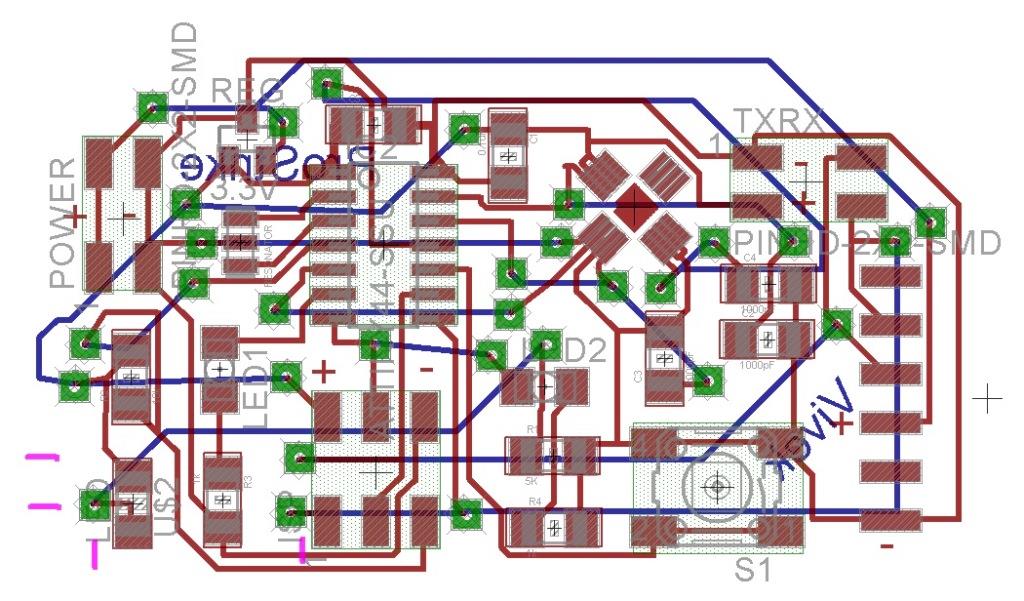
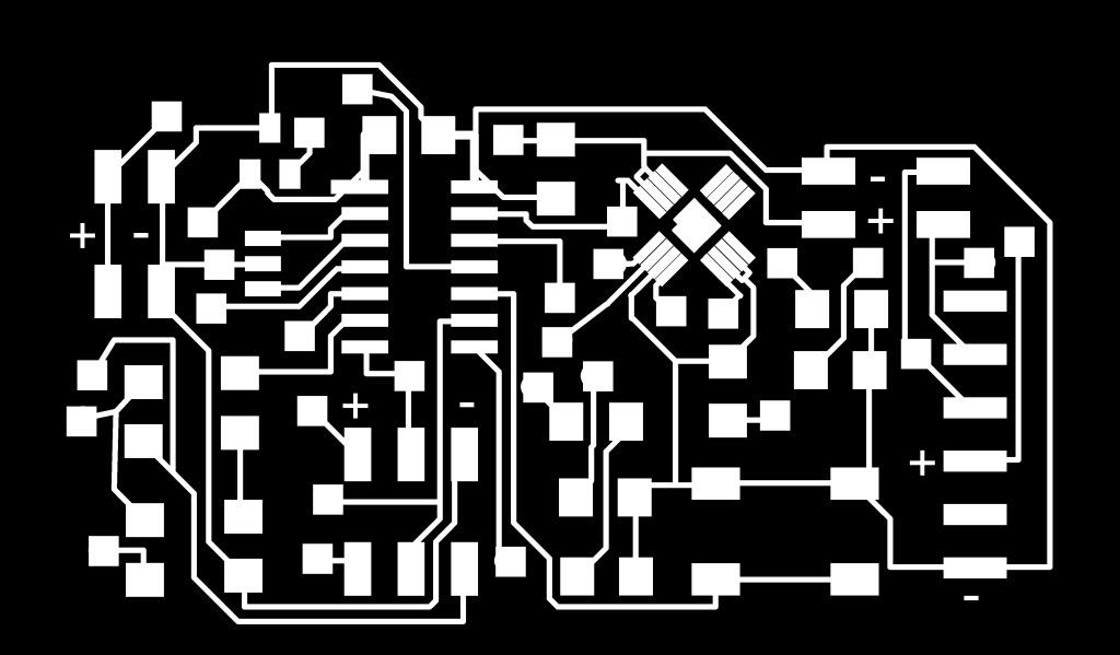
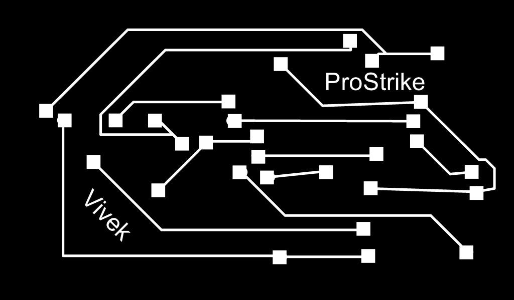
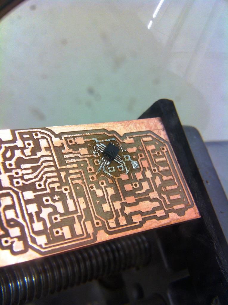
The 3-axis high-g accelerometer circuit
Here too I made a two sided design with eagle with ADXL377. Soldering the tiny 16-lead, lead frame chip scale package (LFCSP_LQ) was easy once I got the traces wide enough. I had to use the 10 mil end mill bit
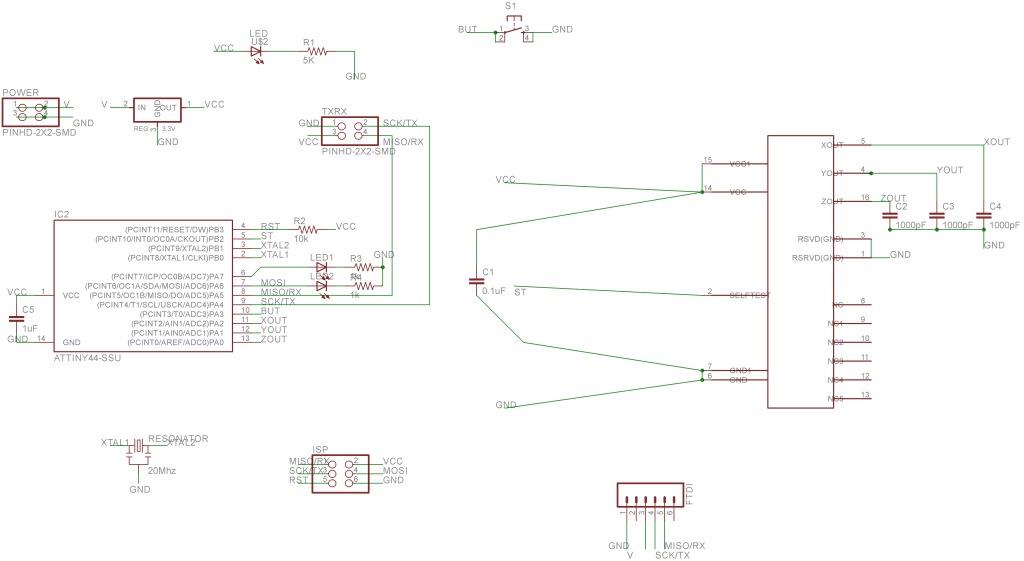
I also used Tk, modified Neil's code to create a python interface to visualize my 3-axis accelerometer circuit output. I serially sent out gx, gy, gz which were computed and averaged out in the circuit
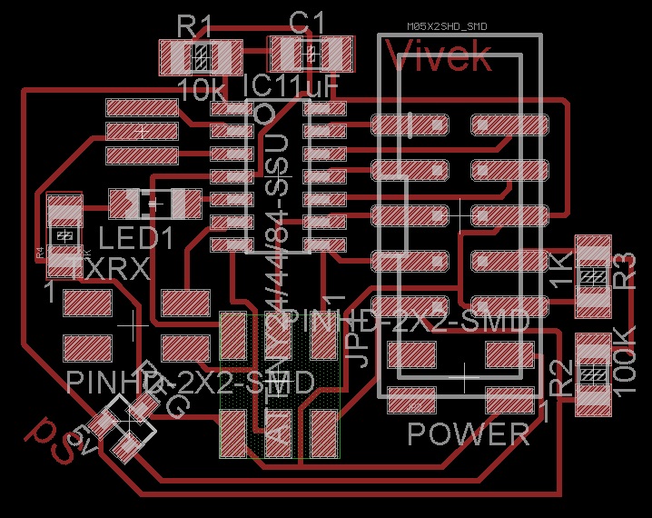
LCD Output interface
I made an LCD output circuit which was intended to communicate with the two accelerometer circuits serially. I added a TX/RX pin block in it. The circuit worked but unfortunately in trying to assemble it together in the 3D printed endlosure I broke the LCD connections!
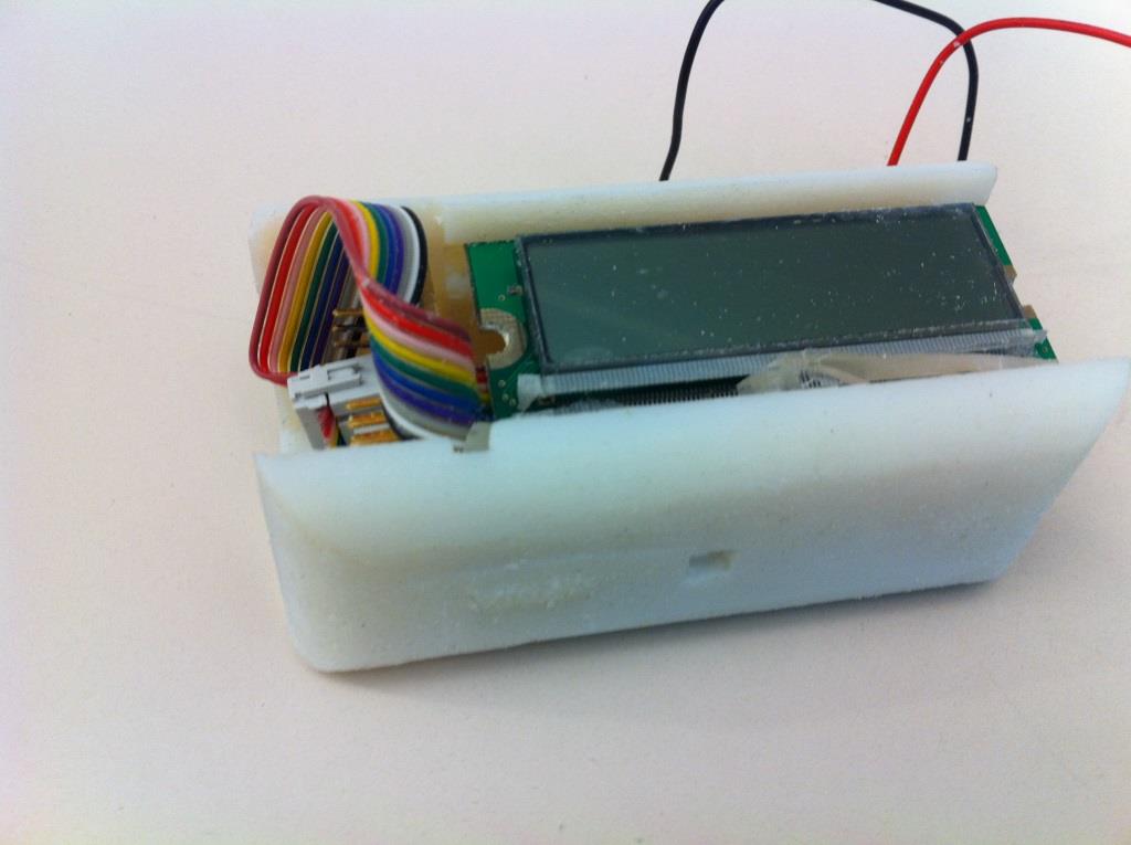
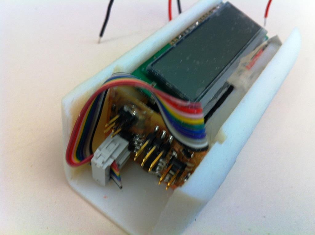
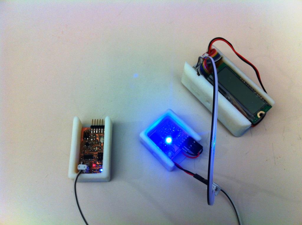
Assembly
In the end, this is what the 3-circuits partially assembled together looks like. They are powered by a single battery source and would have a common serial bus.