Will Patrick
How to make almost anything
Week 3
3D Printing and Scanning
Overview
It's 3D printing week! I feel like whenever I tell someone I'm studying digital fabrication, he or she says, "like 3D printing, right?" And, I'm like, "well, sort of..." I appreciate Neil's view that 3D printing is great but is practically constrained by a number of factors: gantry size, resolution, print time and material type (to name a few). It's not the panacea that mass media makes it out to be. So, I'm glad we're just spending one week on 3D printing.
The project this week has two parts. First, we will design and build a 3D printed part that could not be made subtractively. For example, a model boat in a bottle could not be built by a CNC mill or another subtractive technology because the glass bottle obstructs the fabrication of the boat. However, (in theory) an additive process could fabricate the boat and bottle layer by layer, creating both at the same time. This ability to create complex geometries for no additional cost is probably the best advantage of additive manufacturing.
What am I planning to build this week?
For my project this week, I'm planning to design cubes that can be assembled by magnetic attraction. The idea is to design cubes where the magnetism of each face can be "programmed" by inserting a certain number and orientation of permanent magnets. These cubes could then be assembled into structures simply by pairing each cube face with it's complementary face. One idea I have for my final project is to design a projectile launcher that can build a structure by launching these magnetic cubes in a particular, precise pattern.
In the second part of the assignment, we're tasked with 3D scanning an object. I've never 3D scanned an object and look forward to playing around with 123D Catch from AutoDesk, the Konica Minolta 3D laser triangulation scanner and the NextEngine 3D scanner which uses array illumination.
Similar to Week 1, a major focus this week will be on learning a new design tool. In Week 1, I learned how to use Grasshopper, a visual scripting plug-in for Rhino that is used to create parametric designs. While pulling around and connecting primitives in Grasshopper, I couldn't help but think, "Why am I not coding this?" So this week, I'm doing the assignment using Kokopelli, a 3D scripting language built on Python. It was built by Matt Keeter, a former HtMAA student and researcher in CBA who is now a TA for our class.
Designing the cube
To start building the magnetic cubes, I first shopped online for magnets. I eventually settled on buying a few different sizes of nickel plated neodymium iron-boron core magnets. Neodymium magnets are the strongest type of permanent magnet that's widely available and are also really inexpensive. A really great place to learn about and shop for Neodymium magnets is K and J Magnetics. They have really interesting force vs. distance calculators and a huge selection of sizes and strengths. I ended up buying this 100 pack of quarter inch diameter off Amazon, mostly because of the free 2-day shipping from Amazon (damnit, Amazon you've pulled me in!).
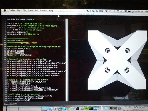
Using Kokopelli
Next, I got started using Kokopelli (download here). Overall, I really enjoyed the experience. It felt very similar to writing markup language for a website; there's a sense of immediate gratification when you can visually see you're code working. Coding the struture felt so much more intuitive. Generating a model by executing a sequence of instructions rather than creating a tangle of components and wires used in Grasshopper just makes a lot more sense to me. It was also faster. It's quicker to type "a*b" when you need to multiply two variables rather than pull down a multiplication component in Grasshopper and wire it up. If you have any programming experience and are interested in doing some scripting-based generative design, I think you should check out Kokopelli before jumping into Grasshopper. Kokopelli is also free! All of that being said, I didn't do any heavy lifting with Kokopelli in this project; it's possible that it may crash or slow down while rendering large structues. It's also developmental software, which means you don't get any creature comforts like auto-save. Anyway, two thumbs up for Kokopelli.
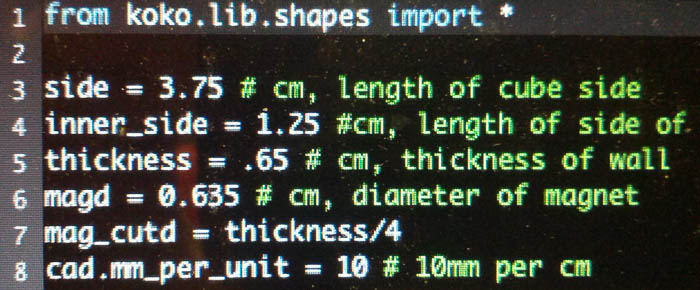
One of the big advantages of Kokopelli is being able to parametrically drive 3D models. For my cube design, I immediately set up a few parameters to drive the design, including cube side length and magnet diameter.
Establishing parameters in Kokopelli
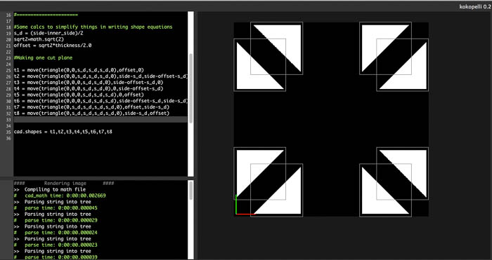
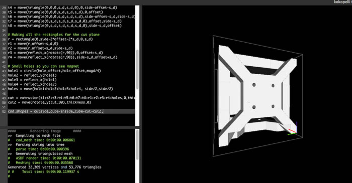
My design strategy was simple: build the first side of the cube and then copy, rotate and move the other 5 sides into their correct places. Feel free to check out the code (below) to see exactly what I did. Here are a few pictures to get a sense of what using Kokopelli is like:
Creating a cutting surface to make the side of the cube.
Using Kokopelli
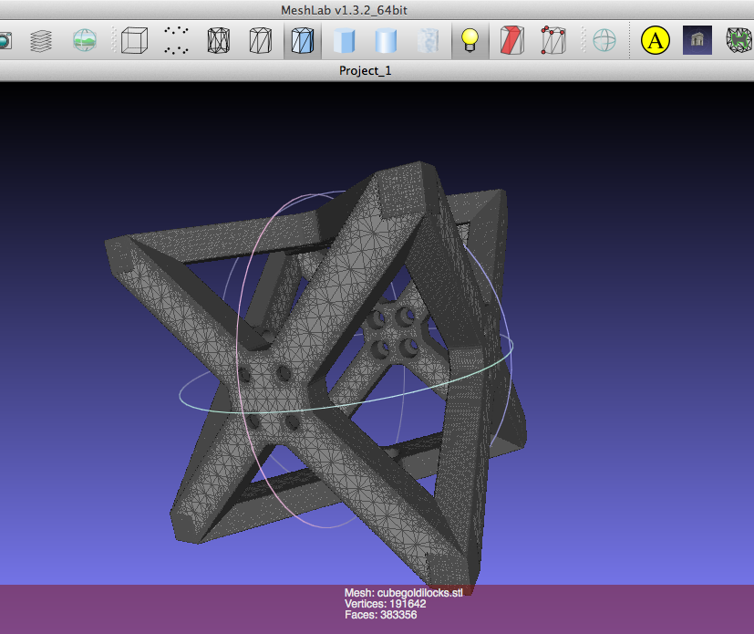
I had a few issues with Kokopelli when exporting to STL. Using the default value of 10 pixels per mm, I created gigantic STL files - on the order of 500MB - 1GB. I realized that units are default set to inches (the default); after changing to cm units and scaling down the pixels to mm to 2 my STL was a healthy 15-20MB - but at least manageable. I then visualized the STL in MeshLab - an open source, cross-platform mesh tool that you can download here.
The STL file visualized in MeshLab
Printing and finishing the cube
Using the Form 1
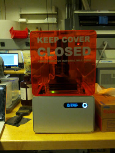
To print the cube, I decide to use the Form 1, the first stereolithography machine released by Form Labs. I've never 3D printed using SLA so I was quite interested in using the process.
The Form 1
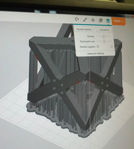
I got started by uploading my STL file into the Form 1 software package. For the first print, I went with a cube diameter of 7.5cm. I didn't need to change any of the settings from the default. I made sure to add supports into the structure since the cube has considerable overhangs. Note: the Form 1 adds support material by using adding in a coarse structure that can be chipped away in post-processing (similar to using the MakerBot or other single material FDM machines). Tom from CBA helped me ready the machine by checking the fluid levels, cleaning hard, UV-cured material off the top of the machine and collecting small pieces of material floating in the resin reservoir. Once ready, we pressed print, and off the Form 1 went.
STL with support added in Form 1 software
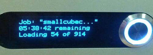
Upon starting the print, the first thing I noticed was the print time: 20 hrs. I came back 4 hours later to check the print. Part of the structure had been printed but the support structure had a problem; only part of the support had printed - new layers of support were not binding to the existing supports. Tom and I stopped the print and took out the partially finished job.
Partially printed cube on Form 1 printer
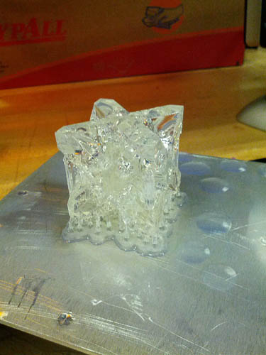
I decided to give it one more shot. To simplify the supports, I made the structure significantly more compact with a side width of 3.75cm.
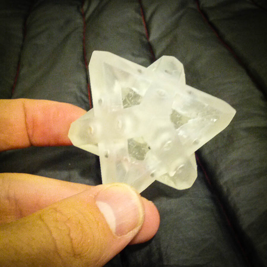
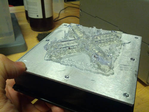
I came back 6 hours layer and the print was finished. It looked like this.
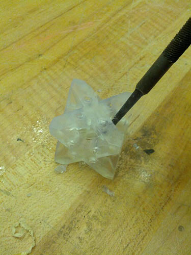
The part required significant post-processing to remove the support material. I first dunked it the isopropyl bath, shaking it for 2 mins and then letting it soak for 10 more minutes. The alcohol helped remove the stickness of the part and loosened the supports. To remove the supports, I used a narrow file. I jammed the file in between the "X"s in the structure occasionally using a mallet to drive the file into support material, cracking it. It was a rather brutal process and in retrospect, I wish I had reduced the thickness of the structure. After removing the support and filing down some of the internal edges, I repeated the isopropyl bath and then finally cleaned the piece. The magnets arrive tomorrow morning; the will hopefully fit snuggly into place.
Cracking off support using a file
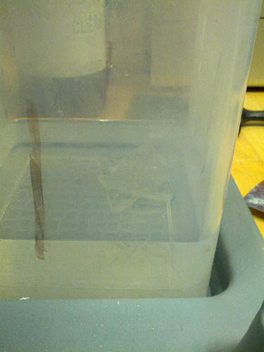
Soaking the print in an alcoholic bath
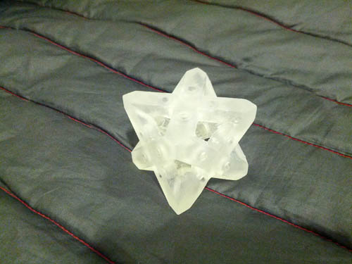
Finished, cleaned part
3D Scanning Sunglasses
First attempts using 123D Catch
I love the idea of being able to use my cell phone camera to create 3D models so I really wanted to test out 123D Catch from AutoDesk. 123D Catch is a free web application where you can upload a set of images of an object and the software will attempt to stitch the images into a 3D rendering.
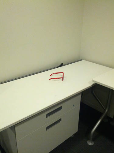
I started off by trying to create 3D models of several objects around my office: my finger, a servo, a stepper motor, a pen container and red sunglasses. I set up the objects in the corner of the room on my white table. The results were comical as can be seen below.
Original photography setup
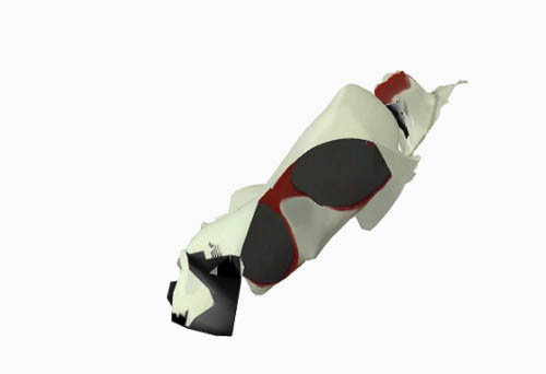
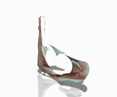
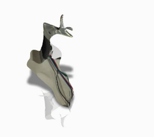
Distorted images created by 123D Catch using photos captured using the first setup
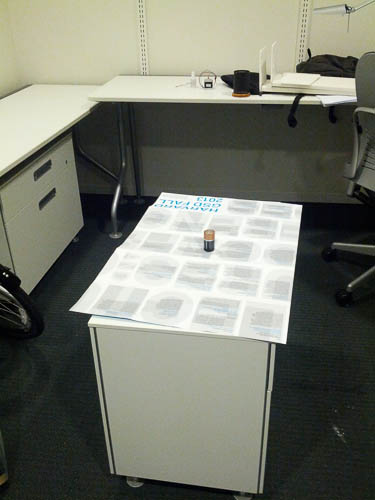
I then did a little Googling to better understand how 123D catch works and how I could improve my results. I found that the stiching algorithm uses many different references around the room to orient the position of the camera and object. So it's actually better to have other objects around the table. In my second attempt, I added a poster to the table and a few random objects other than the object being photographed. I also moved the table to the center of the room so I could more easily walk about the object and take photos at regular intervals. The results were much better but not excellent.
Improved photography setup
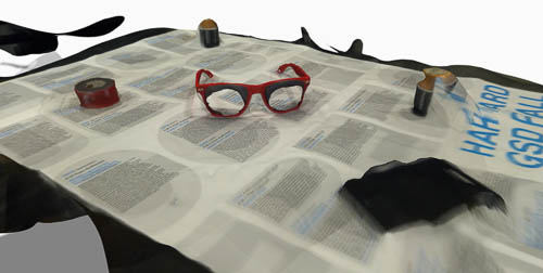
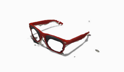
Images created by 123D Catch using photos captured using the improved setup
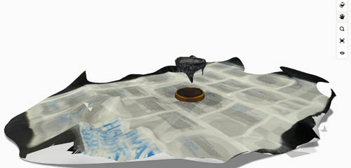
I tried my best to clean up the mesh in the 123D Catch program. Here's the result.
Konica Minolta
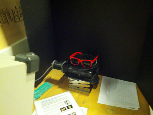
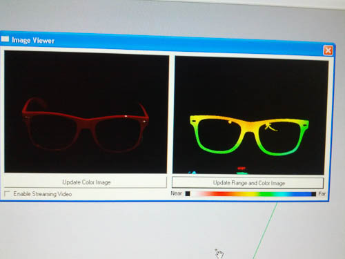
Next, I moved downstairs to the lab to try out the Konica Minolta 3D scanner. I used the red sunglasses as my test piece. Using the scanner in GeoMagic was relatively straightforward. The main challenge was manually focusing the laser to the correct distance. 560mm was the magic number for me. Here's a view of the test set-up and a view of the depth and photo imagery of the glasses once the laser focus distance was calibrated.
The setup using the Konica Minolta scanner
Depth and Visual Imagery of the glasses. Yellow = good
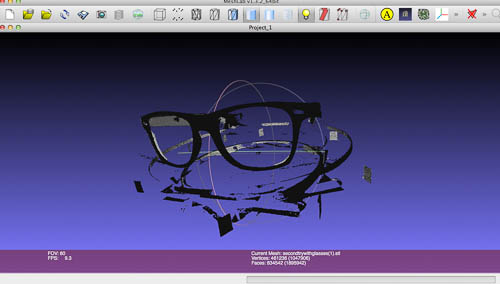
I then scanned the object 4 times, rotating 90 degrees after each scan. The resulting STL uploaded into MeshLab looked like this:
Unadultered STL from the Konica Minolta scan
"Fixing the mesh"
At this point, I set out to make the mesh printable. This was my first time ever adjusting a 3D mesh so I had no idea what to do. I ended up using a combination of GeoMagic, MeshLab, NetFabb and Meshmixer. It's not worth repeating all the steps I took - because I'm sure I took a circular path. This is definitely an area I really hope to build my knowledge in the coming weeks...
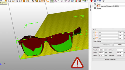
Orienting the mesh and cleaning away the random surfaces in NetFabb
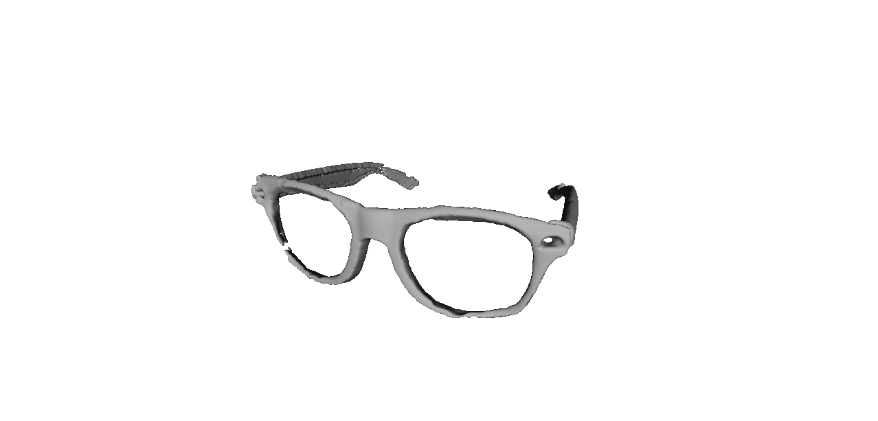
"Finished" mesh
Printing the 3D glasses model
I set up the glasses to print on the MakerBot Replicator. The glasses are printing as we speak and we'll see how they turn out in the morning!
Downloads
cube.cad — Kokopelli file for cube — Updated October 1, 2013