Step-by-step
instructions for preparing your file and milling it with ShopBot
First, open
partworks3D and upload your STL file.
You will
reach the following screen:
 =
=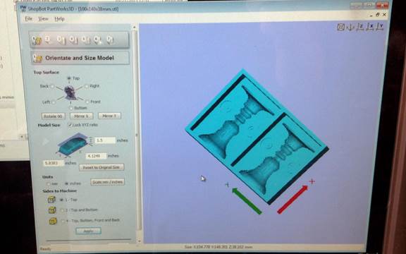
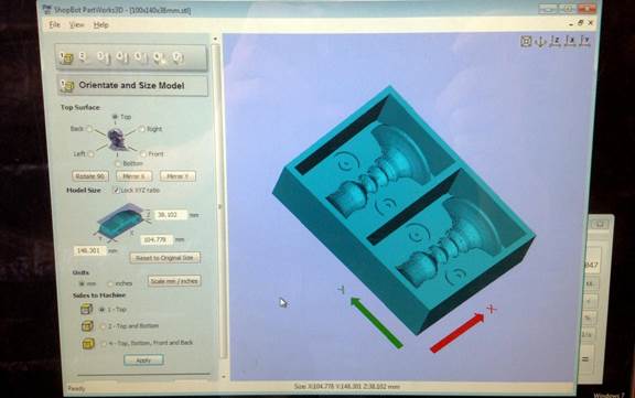
Make sure
your model is oriented correctly and that size is right (either mm or inches).
To get it in
the right X\Y plane, switch between the “top surface” options.
To fix size,
play with the units radio buttons and the “reset to
original” button until you get it right. Remember that 25.4 mm is 1”.
Next step is
material size and margins.
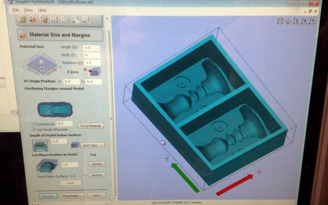
Here you
define the size of the wax piece you are milling. As always, it is useful to
measure it from the top of the front right corner. Once you click “apply” a
wireframe will appear on screen that matches the measurements you used.
Pay attention
that you use the same unit system (mm or inches) as you did in the previous
screen. If you don’t see a wireframe it probably means your units are off.
If you don’t
model your design already within a box frame, you can use the “machining
margins…” and “cut plan position” to define the boundaries of your work area (walls
and floor for your model). Default settings are shown above. If you use a
non-zero margin, it will appear as a gray area surrounding your model.
Once you’re
done click “next”.
Next screen
is the roughing toolpath (the toolpath
used mostly to excavate most of the wax out).
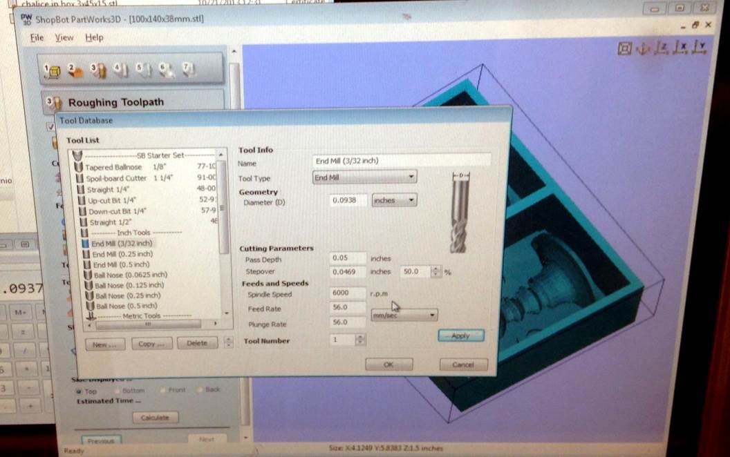
First you
need to choose the tool you’re using. In this case I used the 3/32” end mill. It
wasn’t on the list so I had to click “new” and define its settings.
For overlap,
Partworks accepts any value between 2-50%. The higher
the overlap, the higher the resolution and the longer it takes to finish the
job. For roughing you should use a high stepover
(=low overlap).
For wax (and
foam) the spindle speed should be 6000 rpm.
The feed
rate for 1/8” end mill is 75mm/sec, so to use a 3/32 end mill you need to multiply
that number (75) by the ratio of the end mill size (1/8=4/32, so ratio is 3/4).
That gives a feed speed of ~56mm/sec. double check the units before you click
ok.
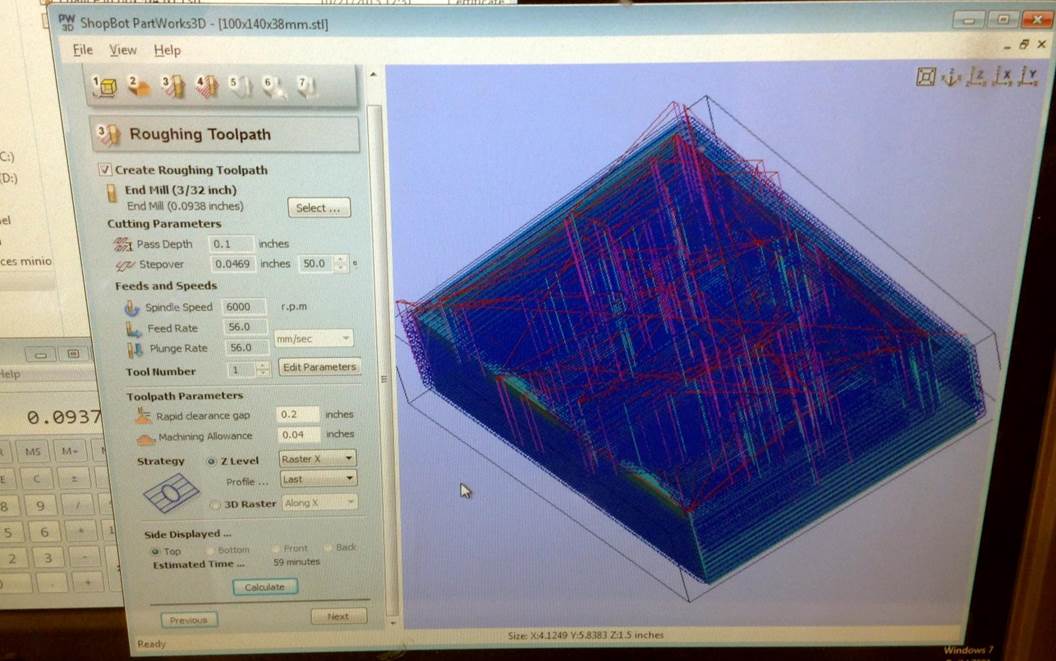
After you
pick the tool you need to choose strategy. For roughing it doesn’t matter a lot
if you pick raster X or raster Y, but it might be useful to remember your
choice for the next step (finishing) to select the opposite direction if you’re
short on time.
Click calculate and it will show you the path and estimate the time. Partworks
tend to down-estimate time, so be comfortable adding at least 10% to the number
you get.
Click “next”.
This is the
finishing toolpath screen.
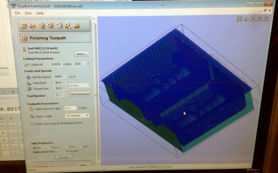
Here you can
select a different tool (I didn’t) and change the stepover\overlap
percentage.
For raster
angle the default is 45 degrees, and you have the option to add an extra path
at 90 degrees to that, which make this phase twice as long but gives higher finish.
If you’re short on time, you can select the Y axis (if you choose X for roughing)
or vice versa.
Click calculate,
see timing, and click “next”.
The next
screen (#5 on the partworks3D workflow) is for cutout and is largely irrelevant
for what we are doing, so just click next.
On the next
screen (#6) you can animate the toolpaths. Use it to
check for any missing features on your model and change tool settings (or go
back to the drawing board) accordingly.
Last screen
should look like this:
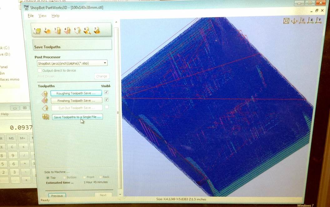
You should
save your toolpaths in the default (first option)
setting: arcs-inches-alpha. Make sure both the roughing and finishing
checkboxes are marked, and save to a single file.
Here you can
also see the estimated total time it should take (again, it is usually a bit
too optimistic).
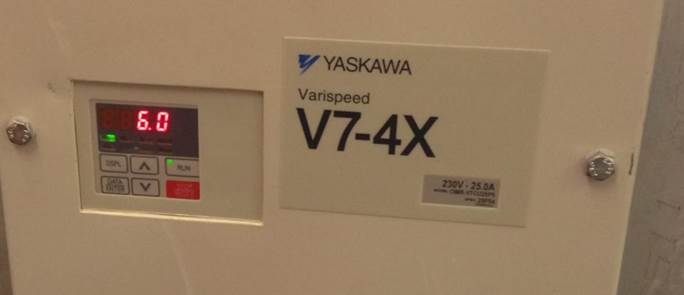
Lastly, at
least in IDC, make sure the speed on the machine itself matches your settings.
For comparison,
here are videos of roughing
in ShopBot VS roughing in Modella.
Enjoy!