I used the 123D Catch app on my phone to create a 3D model of the Bridgeport mill from the Media Lab shop. Unfortunately, the file is huge (>100MB) so I couldn't attach it to the class pages and render it with three.js, and the 123D catch embed doesn't seem to be working right now, but you can view an interactive version of the model here or download it here.

I've used Catch many times before, most notably on a trip with my Instructables coworkers to the wax museum, where I got this sweet Donald Trump model. It seems to work best for things ranging in size from a shoebox to a person, but the cool thing about it is that it can kind of do some architectural-scale stuff as well.
I took about 35 photos of the Bridgeport mill, circling around it at many different heights to get good coverage of the object. Here is a sample of my photos.
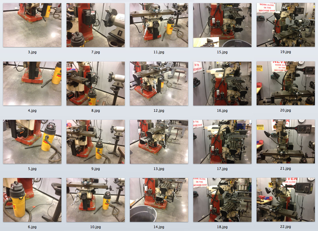
Then I uploaded the photos through the 123D Catch app and let Autodesk's servers do the rest. The model took about 2 hrs to render. In the end, the model is cool looking, but not very useful. It has a lot of extra geometry in places that are not very useful, and there are quite a few parts of the model that are skewed in strange ways, or floating in mid air. It would take a ton of work to clean this model up and do something useful with it. I've tried other scanning techniques in the past, but even a 50k scanner doesn't do a great job at capturing what you want from an object. It's a bummer - I use 2D scanning frequently to trace irregular 2D features from physical things, but 3d scanning needs at least a few more years to catch up.
One of the biggest obstacles with 3D printing is the small print volume and slow print times for large objects. With this project I wanted to try to 3D print something in a condensed state that can expand to something even larger than the printer that made it. There have been some interesting projects that have started exploring this idea, most notably a folding algorithm used by Nervous System to fold a hinged design into a compressed state before printing.
Hoberman spheres are something you are probably familiar with, though you might not know their name - they're these things. Using a variation on the classic scissor mechanism, these mechanisms produce uniform radial expansion in 2D or 3D. The Hoberman spheres you can buy in stores are usually icosidodecahedrons, but the mechanism will work in may other shapes; I used a dodecahedron as my base shape because I think regular polyhedra are pretty.
These mechanisms were printed on the Envision 3D printer, which uses a wax support material. Since the support can be melted or dissolved off the models, you can print a complete mechanical assembly in one piece.
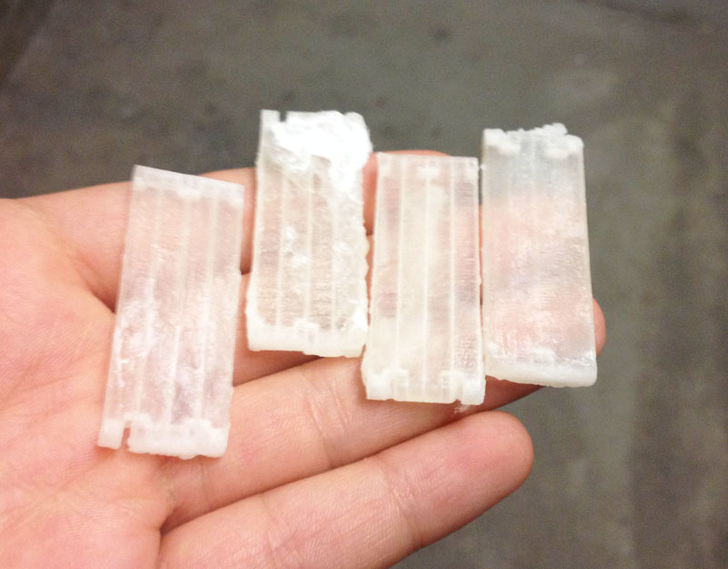
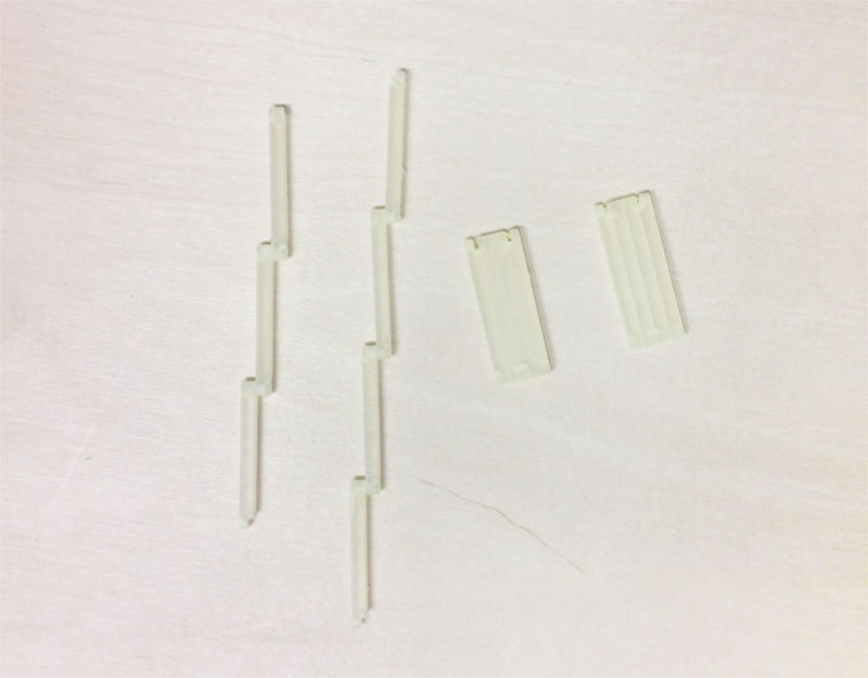
The mechanisms in the Hoberman sphere are all simple revolute joints made from a pin hinge. I started this project off by doing some tolerance tests, to find the right offsets to use for my mechanism so that I could print it in one piece. I did four tests, two at 0.25 mm spacing and two at 0.125mm spacing, using a few different diameters in the central pin of the joint.
The images below show the tests when they came out of the printer and after the supporting wax was removed in a hot mineral oil bath. I found the 0.125mm spacing tests did not move at all, but the 0.255 mm tests moved nicely, without too much play. I also found that the central pin of the joint should be at least 2.5 mm.
I did a quick print of a 2D Hoberman mechanism to see if everything was working correctly. Each link in a Hoberman mechanism must be bent to keep all the joints moving in a perfectly radial motion during expansion. The angle of the link bend is given by the following equation:
bend angle = 180 - 360/n
where n is the number of scissor hinges in the mechanism (n = 8 in the image above), and bend angle is measured in degrees.
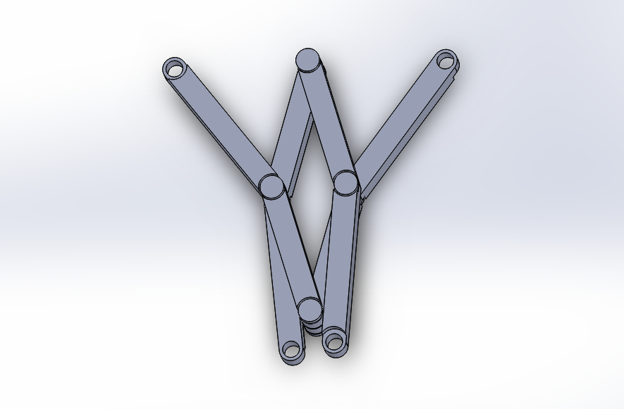
I modeled the link and a simple pin joint parts in Solidworks, and constrained them in a sub assembly to create one section of the mechanism. Then I combined many of these sub assemblies together to create the entire 2D mechanism. At first I was having trouble with my sub-assemblies not moving in the higher level assemblies, but I found a trick to solve that here.
After soaking in hot mineral oil for a while, and baking at 150 degrees F, the resulting mechanism moved really nicely (shown in the gif below).

The basis of my 3D Hoberman mechanism is a dodecahedron - a 12 sided regular polyhedron, made up of pentagon faces. The equation from the last step gives the bend angle for a link in a Hoberman mechanism that forms a complete circle, repeated here:
bend angle = 180 - 360/n
The dodecahedron shape doesn't contain any sets of edges that for great circles around the shape, so I generalized this equation for maintaining a constant angle as the sphere expands.
bend angle = 180 - theta/n
where theta is the constant angle to be maintained, n is the number of scissor mechanisms, and bend angle is measured in degrees.
At each vertex in the dodecahedron, there are triangular joints whose normals remain constant as the mechanism expands. At first I thought this added a lot of complexity in the calculation of the bend angle of the links since there are expanding mechanism parts mixed with rigid triangular hinges, but it turned out to have no effect on the equation above.
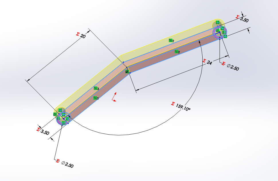
In the case of a dodecahedron, the angle between adjacent vertices is 2*arcsin( sqrt(3)*( sqrt(5)-1 ) / 6) =~ 41.8103 degrees. My first mechanism had two scissor mechanisms per 41.8103 degrees, so the equation above simplifies to:
bend angle = 180 - 41.8103... / 2
bend angle =~ 159.0949...
I plugged this into my model via Soldworks' Equation manager, I also created two handed types of links with a little extra length on one side of the bend. The idea for the handed design came from looking at pictures of Hoberman spheres. You can see that this extra length helps the mechanism compress better because the triangle linkages (in that link they are using squares) will have space to compress away from the rest of the mechanism.
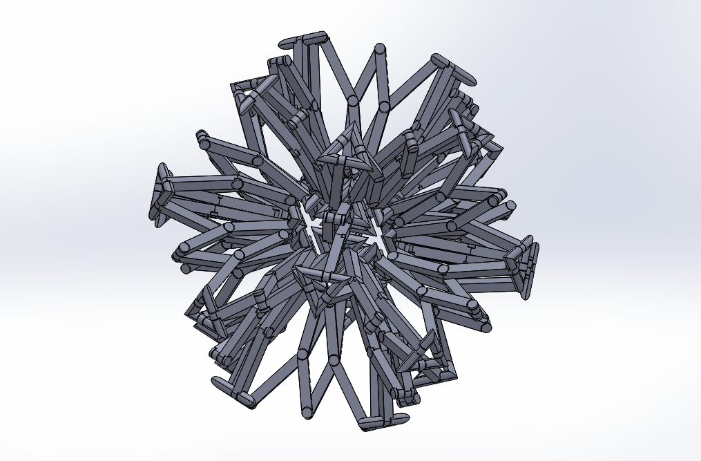
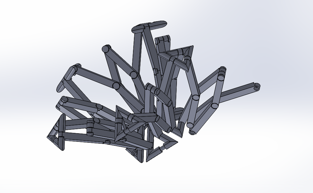
As with the 2D assembly, I used some hierarchy to put the full assembly together. One assembly consists of four links and four pin joints, the next level consists of a set of these scissor mechanisms creating a full pentagon shape, and the final assembly is the complete Hoberman sphere. I found that until the full assembly is put together, it's best to leave all the sub-assemblies rigid - it's possible to get into very strange, physically impossibly configurations when things bend the wrong way that are impossible to get out of with a mouse. Unfortunately, I had to completely scrap an assembly a few times before I learned this.
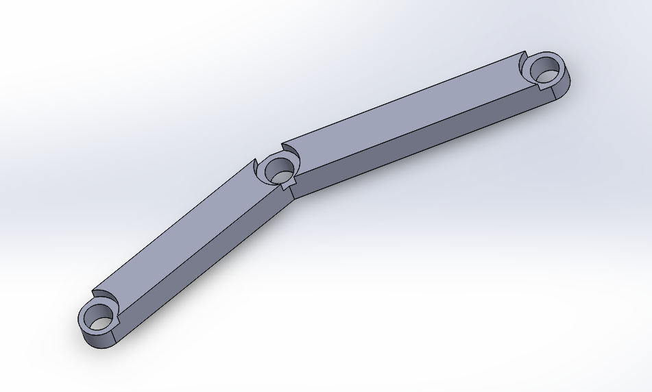
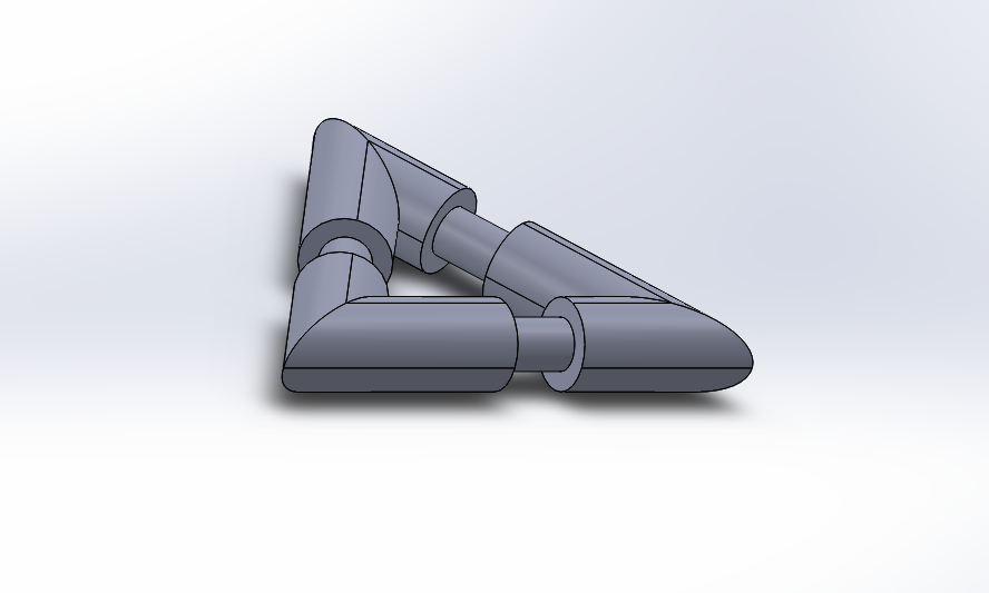
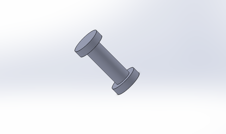
The two joint types for the mechanism are shown below.